Designing, installing, and troubleshooting electrical systems requires the use of various drawings to provide engineers, installers, and technicians with a visual representation of the systems they work with.
Electrical equipment and circuitry are often expressed as symbols and lines, representing various components and connections within a system. The level of complexity in an electrical drawing varies depending on its intended purpose and the personnel working with it.
Design engineers and technicians use schematics to build and troubleshoot complex circuits, while plant operators use single-line and riser diagrams to facilitate switching operations within their distribution system. Knowing how to read and interpret various types of electrical drawings are an essential skill that all electrical workers must posses to effectively carry out their tasks.
The symbols and lines within an electrical drawing convey a language that everyone involved must understand to design, build, and troubleshoot electrical systems. In this article, we will briefly describe several types of common electrical diagrams encountered in the field and explain their purpose.
One-line Diagram
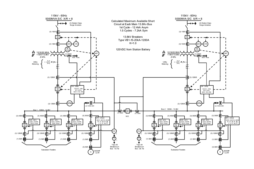
Medium-Voltage Switchgear One-Line Diagram. Photo: General Electric
When you need a bird’s eye view of a power system, the single-line diagram is often the first drawing to consult. Also called one-line diagrams, these drawings illustrate the flow of electrical power or the course of electrical circuits and how they are connected.
Physical relationships are typically disregarded in a single-line diagram; however, they should display all major components in the power system and list all important ratings. System voltage, transformer impedance, interrupting ratings, and fault current are just a few of the basic items included on a single-line diagram.
These drawings should be kept on display in the main control room of a facility to help guide switching operations by identifying feeders and the loads they serve. System voltage, frequency, phase, and normal operating positions are typically included.
Other items, such as instrument transformer ratios and protective relays, can be found on a single-line diagram. If the diagram cannot cover all the components involved, additional diagrams can be drawn in conjunction with the main diagram.
Related: Electrical One-Line Diagram Symbols
Three-Line Diagram
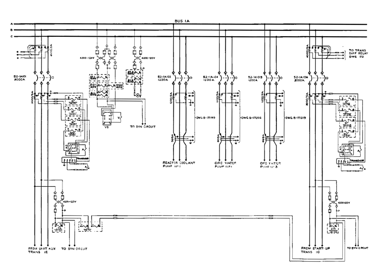
4160V Bus Three-Line Diagram. Photo: NRC.gov
For a more detailed view of an electrical distribution system, a three-line diagram is used to show phase relationship. In polyphase AC systems, these drawings illustrate the various connections for A, B, C, neutral and ground – each represented with their own line.
Three-line diagrams expand on the single-line by providing a basic visual guide for actual feeder cabling, instrument transformer connections, and protective devices. These drawings show how phases are wired and specific winding configurations without regard for their physical location.
Riser Diagram
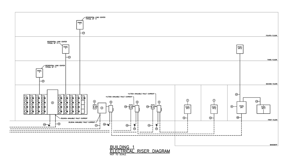
Electrical Riser Diagram. Photo: BGR Engineers.
To help illustrate the electrical distribution system of a multilevel building, the riser diagram is used. These drawings have a similar to relationship to single-line drawings but often focus on how power flows from one level of the building to another.
Riser diagrams show distribution components such as bus risers, bus plugs, panelboards, and transformers from the point of entry up to the small branch circuits on each level. These drawings can sometimes share the layout with alarm systems, telecom, and internet cables.
Schematic Diagram
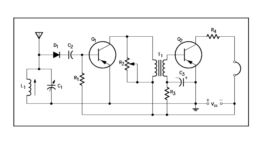
Electronic Schematic Diagram Example. Photo: DOE.gov
The primary purpose of a schematic diagram is to emphasize circuit elements and illustrate how their functions relate to each other. Schematics serve as extremely valuable troubleshooting tools that identify which components are in series or parallel and how they connect to one another.
Components commonly found on schematic diagrams include resistors, capacitors, inductors, diodes, logic gates, fuses, contacts, switches, and more. Each component in a circuit diagram has its own symbol to represent it.
Schematic diagrams should be arranged for simplicity and ease of understanding, without regard for the actual physical location of any component, focusing only on how they connect together. These diagrams should always be drawn with switches and contacts shown in a de-energized position.
Related: Circuit Breaker Control Schematic Explained
Wiring Diagram
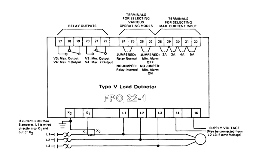
Load Detector Relay Wiring Diagram Example. Photo: Square D.
The main purpose of a wiring diagram is to illustrate all the components in an electrical circuit and arrange them to show their actual physical location. Unlike a schematic diagram, which can be considered a conceptual drawing, the wiring diagram is designed for end users and installers who focus on making connections and troubleshooting components.
Wiring diagrams should identify all equipment parts, devices, and terminal strips with their appropriate numbers, letters, or colors. The designation of terminals and connections between the components is clearly identified to aid in the construction or repair of the equipment shown in the drawing.
Block Diagram
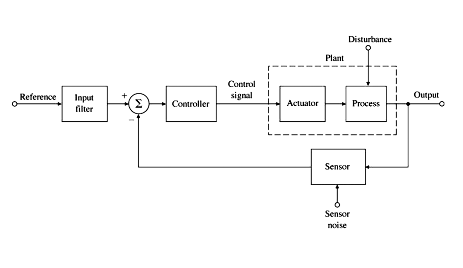
Block Diagram Example. Photo: Mercer.edu
Arguably the most basic type of electrical drawing, block diagrams represent the principal components of a complex system in the form of blocks interconnected by lines that show their relation to one another. These diagrams should not be confused with one-line drawings as they do not convey any technical information, only the major components in a complex system.
The block diagram provides a conceptual idea of how a process is completed without regard for electrical symbols or terms. Each block represents a complicated circuit that can be explained using other drawings such as schematics and wiring diagrams.
Logic Diagram
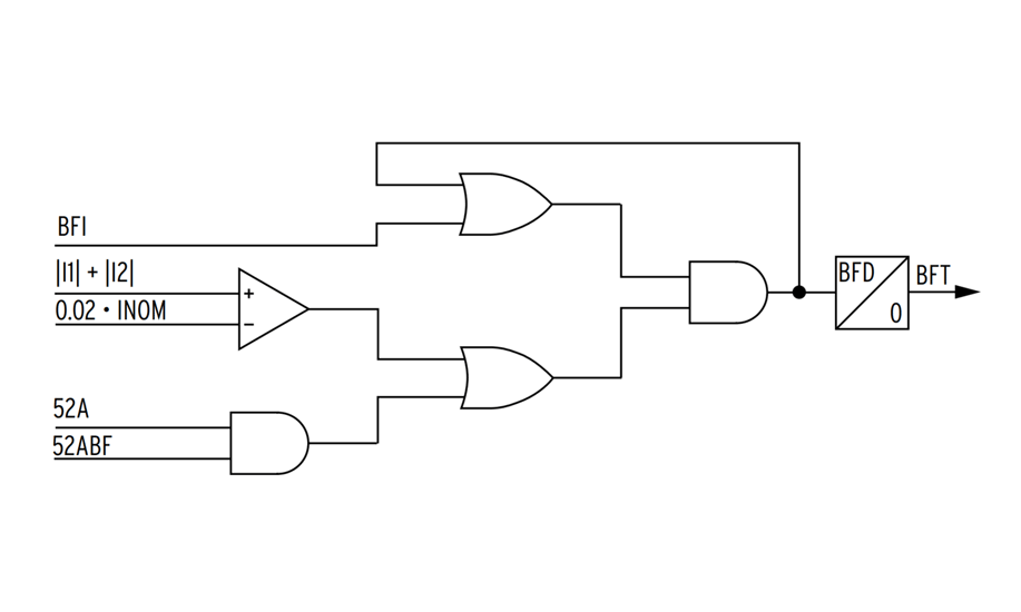
Breaker Failure Relay Logic Diagram. Photo: SEL, Inc.
Modern protective relays utilize logic diagrams to represent complex circuits and processes where the signal is considered in binary format (1 or 0). The logical functions in these diagrams are represented by their respective symbols, while blocks are used to represent the complex logic circuit.
The blocks in a logic diagram are labeled for better understanding without revealing the internal structure, and they are connected by lines representing inputs and outputs for the binary signals. Logic diagrams generally do not depict electrical characteristics such as voltage, current, and power.
Schedules
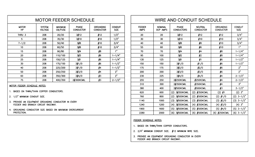
Motor and Feeder Schedule Examples. Photo: Volusia County, FL
When listing items such as feeder breakers and wire sizes for a particular project or piece of distribution equipment, the schedule is used. The term “schedule” can also refer to the dates on which a certain activity is to be completed, usually referenced as a “project schedule.”
In terms of electrical distribution, schedules are often included on switchboard and panelboard drawings to list the number of circuit breakers, their size, and the loads they serve. Feeder schedules are used to help identify the size and number of wires used for the incoming service and outgoing loads within a construction project.
Schedules are usually expressed in tabular form and organized in a self-explanatory way that makes it easy to identify information quickly. The information on a schedule generally does not include one-line or connection diagrams, but it will typically identify this information with reference drawings, legends, and notes.
As-Built Drawings
Whenever a construction project is completed, the “As-Built” is a revised drawing created and submitted by the contractor to highlight any changes made from the initial design drawings during the construction process. These drawings are an exact reflection of a project after it has been completed and should detail the shape, dimensions, and precise locations of all elements within the scope of the project.
Any modification, no matter how small, should be included in the as-built drawings if they differ from those indicated in the original plan. As-built drawings should include a record of approvals to accompany the changes made.
References
- General Electric One Line Diagram
- What are as-built drawings?
- Typical Electrical Drawing Symbols and Conventions
- Electrical Riser Drawing Example
- Electronic Diagrams and Schematics
- Square D Wiring Diagrams for Contactors, Starters, Relays, and Controllers Catalog
- SEL-787 Transformer Protection Relay