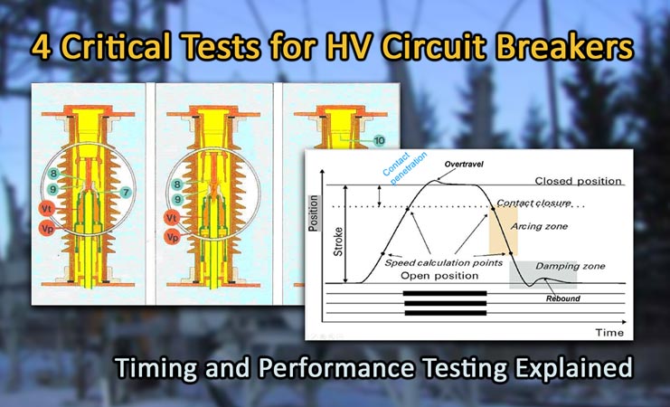
Circuit breakers are among the most complex and critical mechanical components within the electrical power system. They are responsible for interrupting nominal and short-circuit currents, in addition to performing routine changes in the overall system configuration.
Various tests can be conducted on high-voltage circuit breakers to evaluate the operational performance of their different internal components. Regardless of the breaker type—whether it be air blast, oil, vacuum, or gas—it’s important to test their components regularly to help ensure proper operation in the event of a system fault or switching operation.
1. Contact Timing Test
Circuit breakers are equipped with fixed and moving contacts housed within an arcing chamber. The moving contacts are actuated by the operating mechanism to quickly open or close the circuit.
The contact timing test is used to compare the circuit breaker’s contact performance against the manufacturer’s specifications. The breaker contact operations are timed in milliseconds and cycles, then compared with the manufacturer’s specifications to determine the performance of the breaker.

High Voltage Circuit Breaker Interrupter Working Principle. Photo: Wikimedia
There are 6 timing tests that are typically performed on a circuit breaker:
- Open – Simulates a short circuit trip.
- Close – Simulates a close on live circuit.
- Open, Close – Simulates a fast close after short circuit trip.
- Close, Open – Simulates a trip on short circuit after a close.
- Open, Close, Open – Simulates a reclose on a short circuit.
- Close, Open, Close, Open, Close, Open - Simulates a multiple close after short circuit trips.
The main goal of the contact timing test is to measure the exact instant when the contacts change state, as well as to verify the contact travel and speed and identify any contact discrepancies. In addition to contact separation, each contact pole should operate within 1/6th of a cycle of each other, according to IEC 56 3.3.1.
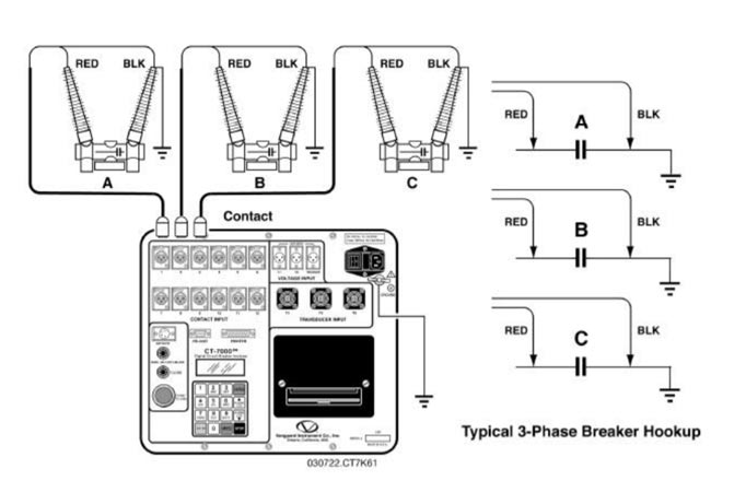
High Voltage Circuit Breaker Timing Test Connection Example. Photo: Vanguard Instruments.
The measured values are compared with the manufacturer’s specified tolerance limits. Many times, the commissioning or acceptance tests are used as reference values. Any deviation from the referenced values can indicate the course of action to be taken based on a proper analysis.
Important Terms
-
Hesitation – A noticeable delay in the acceleration of the contacts from the point where they first part.
-
Maximum dynamic contact gap - The steady state contact stroke plus the overtravel distance.
-
Minimum dynamic contact gap - The steady state contact stroke minus the rebound distance.
-
Opening Speed - The average contact speed from contact part to approximately 75% of the full open gap.
-
Overtravel - The maximum displacement past the resting position that the contacts reach during the operation.
-
Rebound – The measurement from minimum displacement, after the maximum displacement (overtravel), to the final resting position of the contacts.
-
Stroke – The total travel distance of the contacts from resting position in the closed state to the resting position in the open state, or vice versa.
2. Mechanical Motion Test
Motion tests are performed using a circuit breaker motion analyzer equipped with a transducer to check the operating mechanism stroke, velocity, damping, and over-travel against the manufacturer’s specifications. The recorded motion is presented as a curve displaying distance vs. time.
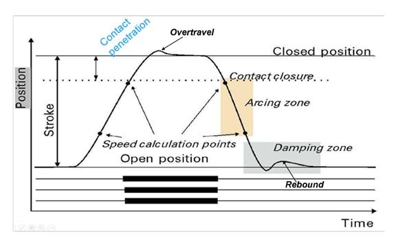
High Voltage Circuit Breaker Typical Motion Trace. Photo: Megger
High-voltage circuit breakers are designed to interrupt short-circuit currents at a very specific speed to prevent voltage re-strike. Slower circuit breaker speeds can reduce the breaking capacity of the main contacts, while faster speeds may cause mechanical damage to the damping components and result in excessive vibration.
The circuit breaker velocity or acceleration curve is calculated from the motion curve captured by the transducer connected to the moving part of the operating mechanism. From this curve, changes that may affect the circuit breaker’s mechanics become evident.
3. Control Circuit Test
A circuit breaker is only as good as the system that controls its operation. Most modern circuit breakers are equipped with electronic coils that actuate mechanisms responsible for opening and closing the main contacts.
These control components are typically operated by substation batteries at low voltage levels and are susceptible to failure if not regularly checked for integrity. During a system fault, a small trip coil that fails to operate can result in catastrophic damage to the power grid, in addition to necessary system outages as upstream devices work to clear the fault.
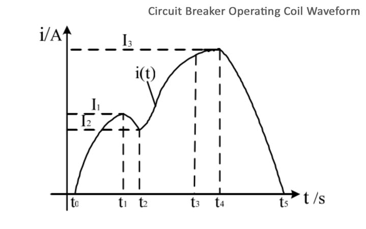
High Voltage Circuit Breaker Operating Coil Waveform Example. Photo: Megger.
Circuit breaker control circuits can be tested by measuring the trip and close coil current, as well as the minimum pickup voltage. The measured values are compared with the manufacturer’s specifications to ensure optimal performance.
Related: Circuit Breaker Control Schematic Explained
The operating coil current waveform provides visual insight into the mechanical and electrical condition of the operating coils. Any significant changes from the baseline test signature should be further investigated.
4. Dynamic Resistance Measurement (DRM)
Contact wear is an important factor that can affect the performance of a circuit breaker, with high resistance between the contacts and contact pitting being prime examples.
A dynamic resistance test can be performed on the contacts, and the resulting resistance chart is used to analyze the circuit breaker contact condition during operation. Tests are conducted by injecting DC current through the contact while measuring the voltage drop and current as the breaker is operated.
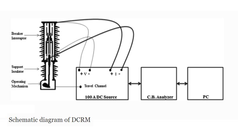
High Voltage Circuit Breaker Dynamic Resistance Measurement Test Schematic
The circuit breaker analyzer is used to calculate and plot the measured resistance as a function of time. When combined with contact movement recordings, it’s possible to pinpoint the contact resistance at each circuit breaker position.
This method is used to diagnose circuit breaker contacts and may also be used to measure operating times. The DRM measurement allows for the arcing contact length to be reliably estimated without the need for dismantling the circuit breaker.
Other Testing Considerations
Mechanical wear and lubrication most often affect the performance of breakers. The ability to trend mission-critical parameters and compare them with factory specifications helps technicians verify proper circuit breaker function.
With so many different styles of circuit breakers available, the tests described in this article only begin to scratch the surface of testing high-voltage circuit breakers. Some other tests that can be performed on circuit breakers include:
-
First trip testing – Used to test “real world” operating conditions by timing the breaker when removed from service.
-
Primary injection testing – High current is injected on the primary side of the breaker current transformers to test the entire relay protection circuit.
-
Static resistance measurement (SRM) – The breaker contact resistance is measured by injecting DC current and measuring voltage drop with the breaker closed.
-
Vibration testing – Acceleration sensors can be placed on the breaker to measure vibration content when opened and closed. The data is compared to known vibration signatures for analysis.
-
Vacuum bottle integrity – High voltage is placed across the bottle to measure the dielectric strength.
-
SF6 leakage – Gas leaks is one of the most common problems found in circuit breakers. Gas sniffers, ultrasonic detectors, and thermal imaging can be used to detect leaks at connection points such as valve fittings, bushings, and flanges.
-
Humidity tests – Moisture within an SF6 chamber can be detrimental to its dielectric properties. Gas samples are run through a moisture analyzer to measure the humidity content inside the breaker.
-
Air pressure tests – For air blast breakers, air pressure tests are performed to verify pressure level, pressure drop rate, and air flow during various operations.
References
- Substation Circuit Breaker Testing
- Timing Test of HV Circuit Breakers using Digital Time Pulse Conversion
- Recommended circuit breaker tests
- Circuit Breaker Testing Guide (Megger)
- Vanguard CT-7000 Manual
- Circuit Breakers and Transducers
- An Overview of Dynamic Contact Resistance Measurement of HV Circuit Breakers