
This guide covers the basic theory and applications for Magnetron Atmospheric Condition testing of vacuum interrupters. Photo: TestGuy.
Vacuum interrupters have been used extensively in modern electrical systems to replace older air-magnetic and oil interrupters for circuit breakers rated 1kV-36kV due to their compact size, faster operating speeds, and higher life expectancy.
Although the service life of a vacuum interrupter is the longest of any other interrupting method, they can still fail catastrophically at any time, resulting in extensive downtime. For this reason, field testing of vacuum interrupters is often used to detect and prevent problems that could eventually lead to equipment failure.
Traditional field testing of vacuum interrupters utilizes the hi-potential test method to evaluate the dielectric strength of a bottle. In this method, high voltage is applied across the open contacts, and a leakage current is recorded. However, this test produces a go/no-go result that does not determine when or if the gas pressure inside the bottle has dropped to a critical level.
Related: 3 Basic Electrical Tests for Medium-Voltage Circuit Breakers
Unlike the hi-pot test, testing vacuum interrupters utilizing magnetron atmospheric condition (MAC) principles can provide a viable means for determining the condition of vacuum interrupters prior to failure. Historically, this type of test could not be conducted in the field because it required large, expensive equipment to generate magnetic fields that are necessary for the test.
Modern advances in testing equipment, such as portable magnetrons and condition-based maintenance algorithms, enable technicians to perform vacuum leak-rate tests in the field, generating quantifiable data that can be used as part of a predictive maintenance program.
Theory of Operation
Even in the best-made vacuum interrupter, there will always be some pressure leakage. MAC testing can prevent unnecessary damage to electrical equipment by predicting the usable life expectancy of a vacuum interrupter based on the condition of internal gas pressure.
To properly understand how MAC testing is applied to vacuum interrupters, it’s important to first review the following principles:
1. Paschen’s Law
The high interrupting capacity of a vacuum interrupter is based on the physical principle discovered by Louis Karl Heinrich Friedrich Paschen (1865-1947). This principle states that the dielectric strength (V) of a gas is a function of the gas pressure (p), the distance between the two electrodes (d), and the type of gas. The result of this function is the vacuum interrupter breakdown voltage.
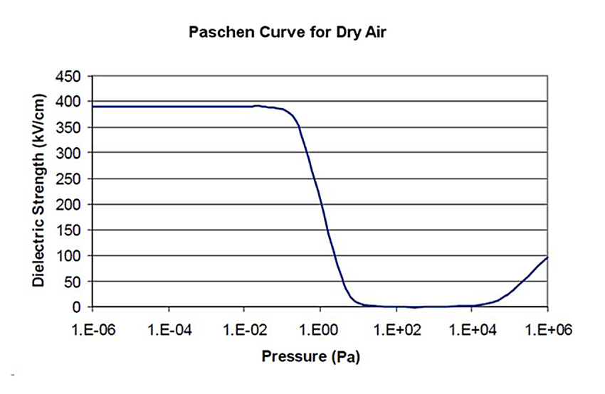
The dielectric strength (V) of a gas is a function of the gas pressure (p), the distance between the two electrodes (d), and the type of gas. Photo: Falkingham and Reeves.
The figure above is the “Paschen Curve,” which shows that the dielectric strength of dry air starts to increase dramatically as the air pressure drops below approximately 10 Pa (10-1 millibar). The dielectric strength continues to rise swiftly until the pressure reaches approximately 10-1 Pa (10-3 millibar) and then remains fairly steady at slightly less than 400 kV/cm (approximately 1000 kV/in).
Based on this curve, the typical VI contact gaps (8 mm to 12 mm) will have dielectric strengths between 320 kV and 1200 kV or higher for vacuum levels between 10-1 Pa and 10-6 Pa. The interrupting capacity in a vacuum interrupter will vary depending on contact design, contact separation, and vacuum level.
The majority of vacuum interrupters are manufactured with an internal pressure between 1x10⁻⁴ Pa and 1x10⁻⁵ Pa. Vacuum interrupters begin to fail a high potential test at internal pressures around 1x10⁻¹ Pa.
The pascal ( Pa ) or kilopascal ( kPa ) as a unit of pressure measurement is widely used throughout the world and has largely replaced the pounds per square inch (psi) unit, except in some countries that still use the imperial measurement system or the US customary system, including the United States.
Vacuum interrupters should be replaced well before reaching the failure point to reduce the risk of injury to personnel or damage to equipment in the event of a catastrophic failure. The overall condition, including contact wear, the number of mechanical operations, and general cleanliness of the vacuum interrupter, should be considered to make an informed decision.
2. Penning Discharge Principle
The vacuum interrupter leak-rate test (MAC test) is based on the Penning Discharge Principle, named after Frans Michael Penning (1894-1953).
Penning demonstrated that when a high voltage is applied to open contacts in a gas and the contact structure is surrounded by a magnetic field, the amount of current (ion) flow between the plates is a function of the gas pressure, the applied voltage, and the magnetic field strength.
Charged particles (ions) can be generated from high voltage supplied across an open vacuum interrupter. When a strong magnetic field is applied to the VI, these ions will move, producing a current across the open contacts.
The ionization current produced is directly proportional to the pressure inside the vacuum interrupter. By comparing this value with a known pressure-ionization current curve, the pressure inside a vacuum interrupter can be easily determined through the Penning Discharge principle.

The vacuum interrupter leak-rate test (MAC test) is based on the Penning Discharge Principle. Photo: Vacuum Interrupters, Inc.
MAC Test Procedure
The magnetic field test is set up by simply placing the vacuum interrupter into a field coil, which will produce a constant DC current during the test. A constant DC voltage, usually 10 kV, is applied to the open contacts, and the current flow through the VI is measured.
As the magnetic field (DC) and the applied voltage (DC) are both known, the only variable remaining is the pressure of the gas. If the relationship between the gas pressure and the current flow is known, the internal pressure can be calculated based on the amount of current flow.
When vacuum interrupters are initially tested at the factory, they are individually placed into a fixed magnetic coil, which is energized by a magnetron. While these types of coils can be used in the field, they are usually very large and expensive, especially in the sizes required for large interrupters.
In addition to their weight, fixed coils like those used in the factory require the VI to be removed from the circuit breaker mechanism for testing. Since removing the VI from its breaker is time-consuming and may lead to equipment damage, flexible magnetic field coils (FMFC) have been developed.
Prerequisites
-
Remove any contamination from the surfaces of the vacuum interrupter to be tested using denatured alcohol and a clean cloth.
-
Open the circuit breaker and verify that the vacuum interrupter contacts are separated within the gap specified by the manufacturer. If the interrupter has been removed from the breaker, a jig can be used to open the contacts. Ensure to protect the movable end of the interrupter from twisting when manually opening contacts.
-
Select the appropriate magnetic field coil. Fixed magnetic field coils require the vacuum interrupter to be removed from the circuit breaker. Flexible coils can be used when the vacuum interrupter is installed in the breaker or when an appropriate fixed coil is not available.
Fixed Coils
Fixed magnetic field coils offer the advantage of a consistent, uniform magnetic field and accurate vacuum interrupter condition measurement. These coils are available in various sizes and require the vacuum interrupter to be removed from the circuit breaker.
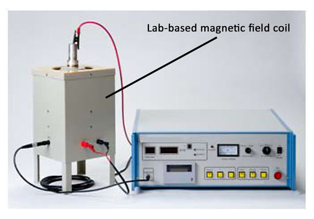
Fixed magnetic field coils offer the advantage of a consistent, uniform magnetic field and accurate vacuum interrupter condition measurement. Photo: Vacuum Interrupters, Inc.
The vacuum interrupter is placed into the fixed magnetic field coil with a small clearance between the VI and the interior of the magnetic field coil. The conductive surface of the vacuum interrupter makes contact with the signal return plate at the bottom of the fixed coil.
A high-voltage clamp is connected to the conductor of the vacuum interrupter, and a signal wire is connected to the fixed magnetic field coil. The Magnetic Coil current source is connected to the fixed magnetic field coil input.
Flexible Coils
Flexible magnetic field coils allow for testing vacuum interrupters that are installed in a circuit breaker or contactor, making them ideal for use in the field. These magnetic coils are available in various lengths to accommodate many different vacuum applications.
When MAC testing vacuum interrupters with a flexible magnetic field coil, it should be wrapped around the vacuum interrupter with each winding tightly against the next; otherwise, the accuracy of the pressure measurement will be affected.
Damage may occur to the test equipment if high voltage is applied to a magnetic field coil. Take special care to keep the high voltage circuit and magnetic field circuit separated.
Placement of the flexible coil cannot be arbitrary; the flexible magnetic field coil should be wrapped tightly around the center of the vacuum interrupter where the contacts separate. Test equipment manufacturers recommend a minimum of FIVE full wraps for accurate results.
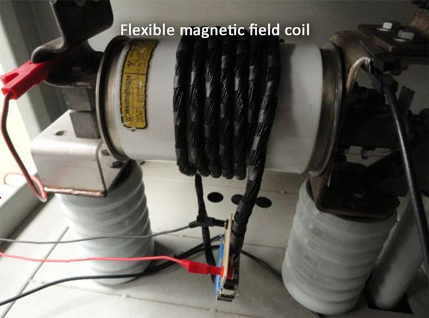
Flexible magnetic field coils allow for testing vacuum interrupters that are installed in a circuit breaker or contactor, making them ideal for use in the field. Photo: Vacuum Interrupters, Inc.
The flexible magnetic field coil should be secured to prevent it from contacting any bus, brackets, or metal endcaps of the vacuum interrupter when testing is in progress. It’s important to understand that not all circuit breakers will be able to physically accommodate a flexible magnetic field coil.
A high-voltage clamp is connected to one conductive end of the interrupter, and a signal wire is connected to the other conductive end. The Magnetic Coil current output is connected to the magnetic field coil input connector.
Running the Test
The test equipment ground terminal should be connected to a suitable ground. Power on the test equipment, enter the test parameters, and start the test. Consult the test equipment instruction manual for specific operating procedures.
Most modern test equipment will fully automate the MAC measurement process. When the test is completed, a pressure result will be displayed. If the pressure in the vacuum interrupter is at an unsatisfactory level or if there are flaws in the test setup, an error or no result will be displayed.
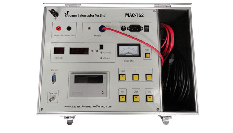
MAC Test Equipment Example. Photo: Vacuum Interrupters, Inc.
Interpreting Results
Each MAC test should produce a pressure result for the vacuum interrupter being tested. The test results obtained are compared to a lab-generated "ionization current - pressure curve.” Using this data together with additional parameters, trends to failure can be predicted using condition-based predictive maintenance.
Note: Repeated testing on the same vacuum interrupter in a short period time will cause the pressure value to reduce. This effect is caused by the capacitance of the vacuum interrupter.
Conclusion
Although vacuum interrupters are expected to last many decades, they are subject to failure just like any other piece of equipment. The projected life of a VI is assumed by measuring pressure leakage over time at the manufacturing stage—an assumption that may not be valid for any given interrupter.
Traditional test methods in the field produce a go/no-go result that does not determine when, or if, the gas pressure inside the bottle has dropped to a critical level. Modern advances in magnetron technology have enabled MAC testing to take place in the field, allowing for a more reliable condition assessment of vacuum interrupters.