
There are many different types of power system study, each with their own special purpose and calculation method. Photo: United States Air Force (CC).
Power system studies are essential tools for understanding the anticipated performance of an electrical system and determining the severity of a fault or other unexpected event.
The data within a power system study can be utilized to safeguard workers by calculating the required level of personal protective equipment and reduce equipment damage by optimizing the fault-clearing capabilities of protective devices.
There are many different types of power system studies, each with its own special purpose and calculation method. Each analysis is unique to a particular power system; any changes within the system can affect the results of the analysis and require recalculation.
This article provides a general overview of the most common power system studies and the differences between them.
Short Circuit Study
The purpose of the short circuit study is to determine the ability of each component within an electrical system to withstand and/or interrupt the system current. Short circuit studies provide an analysis of all possible operating scenarios that will be or have been influenced by the proposed or completed additions or changes to the subject system.
Information contained within the study includes tabulations of the data used to model the system components and a corresponding one-line diagram. Descriptions of the scenarios evaluated, and identification of the scenario used to evaluate equipment short-circuit current ratings, are also included in the study.
Tabulations of equipment short-circuit current ratings versus available fault duties can be found in short circuit studies. The study report should identify the percentage of rated short-circuit current and clearly note which equipment has insufficient ratings.
Coordination Study
The coordination study determines the extent of overcurrent protective device coordination within an electrical system and provides an analysis of all possible operating scenarios that will be or have been influenced by the proposed or completed additions or changes to the subject system.
Related: Characteristics of Circuit Breaker Trip Curves and Coordination
1. Selective coordination
Determines the protective device types, characteristics, settings, or ampere ratings that provide selective coordination, equipment protection, and correct interrupting ratings for the full range of available short-circuit currents at points of application for each overcurrent protective device.
Related: Zone Selective Interlocking (ZSI) Basic Principles
2. Compromised coordination
Determines protective device types, characteristics, settings, or ampere ratings that permit ranges of non-coordination of overcurrent protective devices. In this case, overcurrent protective device coordination may be compromised due to the overcurrent protective devices selected or already installed, or in order to achieve protection of equipment that is selected or already installed.
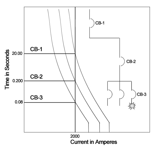
Simplified example of circuit breaker coordination. Photo: TestGuy.
The objective of compromised coordination is to maximize the coordination of overcurrent protective devices to the extent possible based on the type of devices. Determine protective device characteristics, settings, or sizes that provide a balance between equipment protection and selective device operation that is optimum for the electrical system.
Information contained within a coordination study includes a system one-line diagram along with time-current curves, selective coordination ratios of fuses, or selective coordination tables of circuit breakers demonstrating the coordination of overcurrent protective devices to the scope.
Coordination studies also include tabulations of protective devices identifying:
- Circuit location
- Device manufacturer and type
- Current transformer ratios and Range of adjustment
- IEEE device number
- Recommended settings or device size
- Referenced time-current curve
Arc-Flash Hazard Analysis
The purpose of the arc-flash analysis is to determine the arc-flash incident energy levels and flash-protection boundary distances of electrical equipment based on results found in short-circuit and coordination studies. The analysis is performed under worst-case arc-flash conditions for all modes of operation and provides an analysis of all possible operating scenarios that will be or have been influenced by the proposed or completed additions to the subject system.
Related: NFPA 70E Arc Flash and Shock Hazard Boundaries Explained
Arc-Flash Protection Boundaries are determined by conducting an arc-flash analysis. Photo: TestGuy.
Short-circuit and coordination studies are performed to determine the available energy of an electrical system and the expected clearing time of protective devices. The arc-flash hazard analysis selects the working distances and calculates the incident energy at each fault location at the prescribed working distance. Based on this information, the arc-flash hazard PPE category for the calculated incident energy level can be specified, along with the flash protection boundary at each fault location.
Descriptions of the scenarios evaluated and identification of the scenario used to develop incident-energy levels are included. Arc-flash boundaries and tabulations of the data are found within the study and should clearly identify equipment that exceeds 40 cal/cm2.
Any potential system operating modes, including tie-breaker positions, and parallel generation, are also identified within the arc-flash hazard analysis, as these conditions will have an effect on the available incident energy.
Load Flow Studies
A load flow study determines the active and reactive power, voltage, current, and power factor throughout an electrical system. Load flow studies provide an analysis of all possible operating scenarios and identify overloaded equipment.
Included within the load flow study is a tabulation of the data used to model the system components and a corresponding one-line diagram. Descriptions of the scenarios evaluated and the basis for each are also found within the study, along with:
-
Tabulations of power and current flow versus equipment ratings – Identifies the percentage of rated load and the scenario for which the percentage is based, noting any overloaded quipment within the system.
-
Tabulations of system voltages versus equipment ratings – Identifies the percentage of rated voltage and the scenario for which the percentage is based, noting voltage levels that fall outside the ranges recommended by equipment manufacturers.
-
Tabulations of system real and reactive power losses, noting areas of concern along with conclusions and recommendations from the engineer performing the study.
Stability Studies
A stability study determines the ability of the synchronous machines within an electrical system to remain in step with one another following a disturbance. Stability studies provide an analysis of disturbances for all possible operating scenarios that will be or have been influenced by the proposed or completed additions or changes to a system.
Information contained within a stability study includes tabulations of the data used to model the system components and a corresponding one-line diagram. Descriptions of the scenarios evaluated and tabulations or graphs showing the calculation results are also included, along with conclusions and recommendations by the engineer performing the study.
Harmonic-Analysis Studies
The harmonic analysis study determines the impact of nonlinear loads and their associated harmonic contributions on the voltage and currents throughout the electrical system. Harmonic studies provide an analysis of all possible operating scenarios that will be or have been influenced by the proposed or completed additions or changes to the subject system.
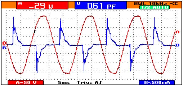
Harmonics in load current and voltage produce distortion in waveforms which cause unwanted effects in the power system. Photo: Wikimedia.
Results of the harmonic analysis study include tabulations of rms voltages, peak voltages, rms currents, and total capacitor bank loading versus associated equipment ratings. Equipment with insufficient ratings is identified for each of the scenarios evaluated.
Tabulations of calculated voltage-distortion factors, current-distortion factors, and individual harmonics versus the limits specified by ANSI/IEEE 519 are provided in harmonic studies. Calculated values exceeding the limits specified in IEEE standards are clearly noted.
Harmonic studies should also include plots of impedance versus frequency showing resonant frequencies to be avoided. Overloaded transformers should be identified within the report, including tabulations of the system transformer capabilities based on the calculated non-sinusoidal load current and the procedures set forth in ANSI/IEEE C57.110.
Related: Power Quality Analysis: Basic Theory and Applications Explained
How Study Data is Collected
Complete and accurate data pertaining to the system to be analyzed is essential for power system studies. Newly installed systems may have studies performed using project drawings and specifications, while existing systems require data to be collected in the field.
Data is often recorded directly from the nameplate of equipment in service. Obtaining power system data in the field should only be performed by qualified personnel, as this work often involves removing access panels on energized equipment to obtain information not found on the nameplate, such as cable sizes and the number of feeders.

Obtaining power system data in the field should only be performed by qualified personnel as this work often involves removing access panels on energized equipment.
Collection of data and final calculations are performed in accordance with the recommended practices and procedures set forth in standards such as IEEE 399, IEEE 141, and IEEE 242. Protective device selection and settings should comply with the requirements of NFPA 70 National Electrical Code. Other applicable standards for power system studies include NFPA 70E, IEEE 1584, and OSHA 1910.269.
Once the system data has been collected, a system diagram is generated, and the equipment information is entered into software designed for power system analysis, and a report is generated. The engineer responsible for performing the study will review and approve the final product.
How Study Data is Interpreted and Applied
The data found within power system studies can be interpreted and applied in many different ways depending on the type of study performed and the reasoning behind the study. Coordination studies, for example, are often used by test technicians during acceptance testing in the field to ensure that protective devices are set correctly and performance-tested in accordance with the settings specified within the study.
Arc flash data is used to generate labels that are applied to system components, informing workers of the available incident energy at a particular piece of equipment and the appropriate levels of Personal Protective Equipment that should be worn while performing work.
Related: Electrical Shock and Arc Flash PPE Overview
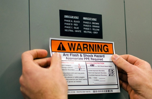
The information found on arc-flash labels are formulated in the arc flash analysis. Photo: Pinterest.
Important Standards
The following standards are applicable to the methods and procedures for conducting short circuit, protective coordination, and other power system studies. Professional judgment must always be used in conjunction with the applicable standards and guidelines.
ANSI
ANSI C57.12.00 – Standard General Requirements for Liquid-Immersed Distribution, Power, and Regulating Transformers
ANSI C37.010 – Standard Application Guide for AC High Voltage Circuit Breakers Rated on a Symmetrical Current Basis
ANSI C37.13 – Standard for Low Voltage AC Power Circuit Breakers Used in Enclosures
ANSI C37.41 – Standard Design Tests for High Voltage Fuses, Distribution Enclosed Single-Pole Air Switches, Fuse Disconnecting Switches and Accessories.
IEEE
IEEE 141 – Recommended Practice for Electric Power Distribution and Coordination of Industrial and Commercial Power Systems
IEEE 241 – Recommended Practice for Electric Power Systems in Commercial Buildings
IEEE 242 – Recommended Practice for Protection and Coordination of Industrial and Commercial Power Systems
IEEE 399 – Recommended Practice for Industrial and Commercial Power System Analysis
IEEE 1015 – Recommended Practice for Applying Low-Voltage Circuit Breakers Used in Industrial and Commercial Power Systems.
IEEE 1584 - Guide for Performing Arc-Flash Hazard Calculations
NFPA
NFPA 70 - National Electrical Code, latest edition
NFPA 70E – Standard for Electrical Safety in the Workplace, latest edition