Electrical testing, in its most basic form, involves applying voltage or current to a circuit and comparing the measured value to an expected result. Electrical test equipment verifies the calculations within a circuit, and each piece of test equipment is designed for a specific application.
It is the responsibility of a test technician to know which piece of test equipment to use for the task at hand and also to understand the limitations of the test equipment they are using. In this article, we will examine the most common pieces of test equipment used in the field.
Electrical test equipment should be considered a source of lethal electrical energy. Technicians must observe all safety warnings and follow all practical safety precautions to prevent contact with energized parts of the equipment and related circuits, including the use of appropriate Personal Protective Equipment.
Multimeter
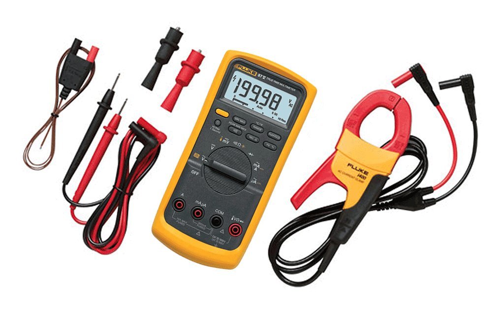
Digital multi-meters are the most common form of meter used today. Photo: Fluke
Also known as a VOM (Volt-Ohm meter), a multi-meter is a handheld device that combines multiple measurement functions, including voltage, current, resistance, and frequency, into a single unit.
Multi-meters are primarily used to diagnose electrical issues in a wide range of industrial and household devices, including electronic equipment, motor controls, domestic appliances, power supplies, and wiring systems.
Digital multi-meters are the most common type of meter used today. However, analog multi-meters are still preferred in certain cases, such as when monitoring rapidly changing values or making sensitive measurements, like testing for CT polarity.
Megohmmeter

Megohmmeters are one of the most frequently used pieces of test equipment. Photo: TestGuy
Most commonly referred to as simply a “megger”, a megohmmeter is a specialized type of ohmmeter used to measure the electrical resistance of insulators.
Resistance values measured by megohmmeters may range from several megohms to several million megohms (terao-ohms). Megohmmeters generate high voltages through battery-powered internal circuitry or a manually operated generator, with outputs ranging from 250 to 15,000 volts.
Megohmmeters are among the most commonly used pieces of test equipment and can be employed to measure the insulation of various types of equipment, including circuit breakers, transformers, switchgear, and cables.
Related: Basic Test Equipment: Insulation Resistance Tester
Low-Resistance Ohmmeter
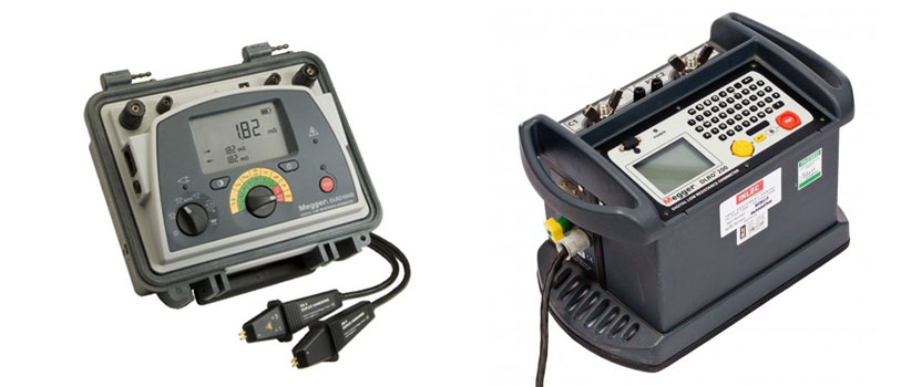
10A DLRO (left) and 100A DLRO (right). Photo: Megger
Often referred to as a DLRO in the field, the low-resistance ohmmeter is used for making highly precise resistance measurements below 1 ohm. Low-resistance ohmmeters generate low-voltage DC currents using battery power, with outputs of up to 100A.
Resistance measurements are obtained using four terminals, known as Kelvin contacts. Two terminals (C1, C2) carry the current from the meter, while the other two (P1, P2) enable the meter to measure the voltage across the resistor. With this meter type, any voltage drop caused by the resistance of the first pair of leads and their contact resistances is disregarded by the meter.
Low-resistance ohmmeters are among the most commonly used pieces of test equipment and can be employed to measure the resistance of various types of equipment, including circuit breaker and switch contacts, cables and busways, transformers and generators, motor windings, and fuses.
Hipotential Test Set (AC/DC/VLF)
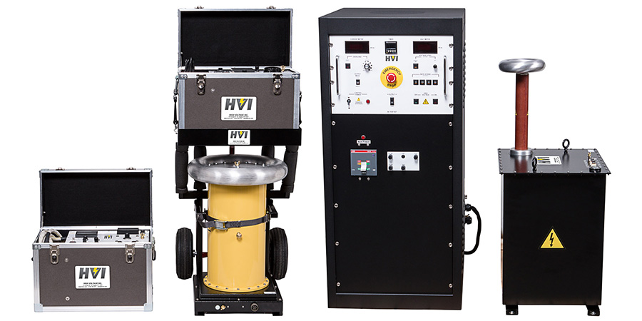
Hipot test sets consist of a high voltage lead, a return lead, and a ground lead. Photo: HV, Inc.
Dielectric withstand (or hipot) testing checks for good insulation in medium and high-voltage equipment, which is the opposite of a continuity test. During this test, insulation is subjected to stress above nominal values to ensure minimal current leakage from the insulation to the ground.
Hipot test sets comprise a high voltage lead, a return lead, and a ground lead. The high voltage lead is connected to the device under test, with all other components grounded, and the resulting current is measured through the return.
If too much return current flows, the internal protection of the test set will trip. The hipot test is a “go, no-go” test, which means that the leakage current must not trip the test set, but there is no specific minimum acceptable value.
The output voltage can vary from 1 kV to over 100 kV, either AC at line frequency or DC, depending on the device under test. Very low frequency (VLF) withstand testing involves the application of an AC sinusoidal waveform, typically at 0.01 to 0.1 Hz, to evaluate the quality of electrical insulation in highly capacitive loads, such as cables.
Related: Power Cable Testing and Diagnostics Overview
High Current Test Set (500A to 15000A+)
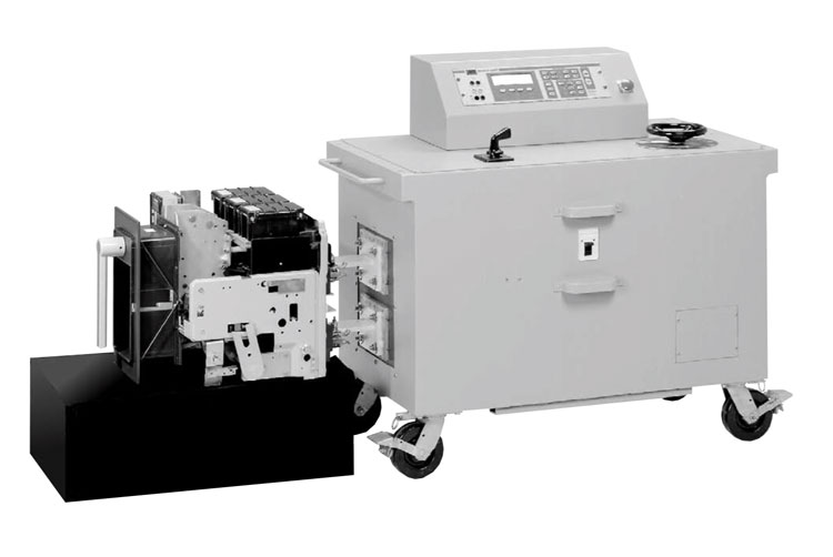
Primary injection high current test set with circuit breaker attached. Photo: Megger
A high current test set may consist of two components known as a “control unit” and an “output unit,” or these functions may be integrated into a single package. Low-voltage, high-current outputs are utilized for primary-injection testing of low-voltage circuit breakers.
The high-current or “primary-injection” test set comprises large transformers that reduce line voltage (e.g., 480V) to a much lower level, typically ranging from 2V to 15V. This significant reduction in voltage enables a substantial increase in available current output, often exceeding 15kA, particularly for short-duration testing.
Current output is regulated by a tap changer and a variable resistor. Integrated timers show the time between current activation and deactivation, indicating the time it takes for a circuit breaker to trip.
Circuit breakers can be directly connected to the high-current test set through a bus or cable. Depending on the size, this type of test equipment can also be used to test ground fault and other current relays by connecting directly to the switchgear bus.
Secondary Test Set
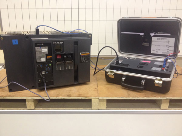
Secondary test sets are designed by trip unit manufacturers to be used with a single style or family of trip unit using a proprietary connection. Photo: Switchserve
Circuit breakers equipped with solid-state and microprocessor trip units can be tested by injecting secondary current directly into the trip unit, rather than passing primary current through the CTs using a high-current test set. The primary limitation of the secondary current injection test method is that it only tests the logic and components of the solid-state trip unit.
Secondary test sets are designed by trip unit manufacturers to be used with a single style or family of trip units, typically using a proprietary connection. Test kits can vary from simple handheld, push-button style designs to more sophisticated “suitcase” units that operate similarly to a primary injection test set.
Handheld units are frequently used to bypass trip unit protective functions, like ground fault protection, when testing circuit breakers through primary injection.
Related: Primary vs. Secondary Injection Testing for Circuit Breakers
Relay Test Set
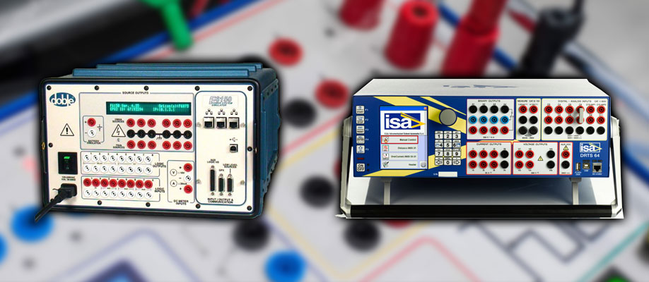
Relay test sets are fitted with multiple sources to test solid-state and multi-function numerical protection. Photo: TestGuy
These are power system simulators used for testing protection devices in industrial and power systems. Relay test sets are equipped with multiple sources to test solid-state and multi-function numerical protection. Each voltage and current channel operates independently to simulate various power system conditions.
High-end relay test equipment can assess not only simple voltage, current, and frequency relays but also complex protection schemes, including communication-assisted line protection and protection schemes that utilize IEC 61850-compliant IEDs (intelligent electronic devices).
Related: Protective Relay Testing and Maintenance Overview
Power Factor Test Set
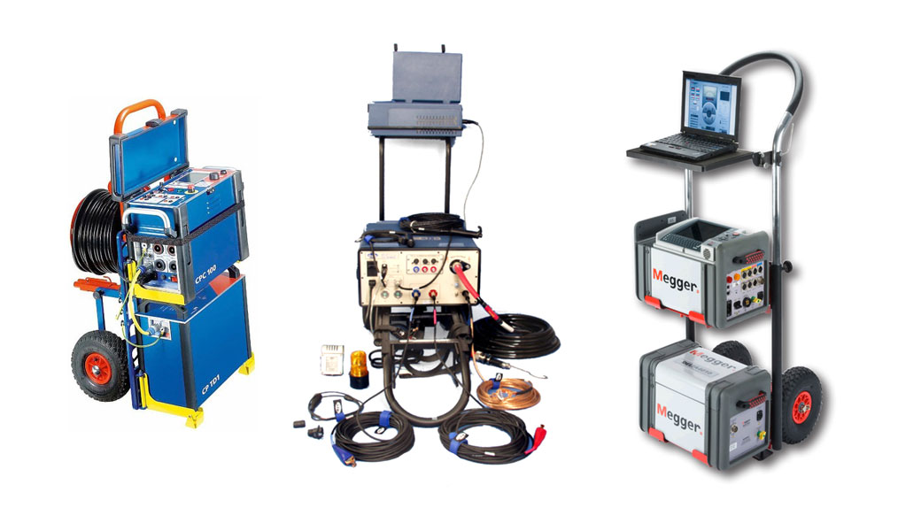
Power Factor Test Equipment Examples. Photo: TestGuy
Power Factor Test Sets offer a comprehensive AC insulation diagnostic test for high-voltage equipment, including transformers, bushings, circuit breakers, cables, lightning arrestors, and rotating machinery.
Test voltages are typically 12kV and below. The power factor test set measures the voltage and current of the device under test using a reference impedance. All reported results, including power loss, power factor, and capacitance, are calculated from the vector of voltage and current.
Tests are conducted by measuring the capacitance and dissipation factor (power factor) of a specimen. The measured values will vary when undesirable conditions are present, such as moisture in or on the insulation, the presence of conductive contaminants in insulating oil, gas, or solids, and the occurrence of internal partial discharges.
Test connections consist of a single high-voltage lead, (2) low-voltage leads, and a ground. Safety switches and a strobe light are included for operator protection, and a temperature sensor is employed to adjust test values. Power factor test sets are typically operated with a laptop computer connected via USB or Ethernet.
Related: 3 Basic Modes of Power Factor Testing Explained
Winding Resistance Test Set
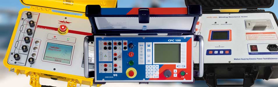
Transformer Winding Resistance Test Equipment Examples. Photo: TestGuy
Winding resistance measurements are a crucial diagnostic tool for evaluating potential damage to transformer and motor windings. In transformers, winding resistance can change due to shorted turns, loose connections, or deteriorating contacts in tap changers.
Measurements are obtained by passing a known DC current through the winding under test and measuring the voltage drop across each terminal, in accordance with Ohm’s Law. Modern test equipment for this purpose employs a Kelvin bridge to achieve accurate results. You can think of a winding resistance test set as a large, low-resistance ohmmeter (DLRO).
Winding resistance test sets typically have (2) current leads, (2) voltage leads, and (1) ground lead. The typical current range of a winding resistance test set is 1A to 50A. Higher currents have been found to reduce test times on high-current secondary windings.
Related: Transformer Winding Resistance: Test Methods and Procedures Explained
Transformer Turns Ratio (TTR) Test Set
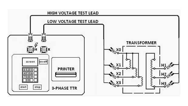
Three-phase TTR testing connection diagram. Photo: EEP.
The TTR test set applies voltage to the high-voltage winding of a transformer and measures the resulting voltage from the low-voltage winding. This measurement is known as the turns ratio. In addition to the turns ratio, these units also measure excitation current, phase angle deviation between the high- and low-voltage windings, and percent ratio error.
Transformer turns ratio test sets are available in various styles and test connections. However, all turns ratio testers have at least two high leads and two low leads. The excitation voltage of a TTR test set is typically less than 100V.
Related: Introduction to Transformer Turns Ratio Testing
Current Transformer Test Set
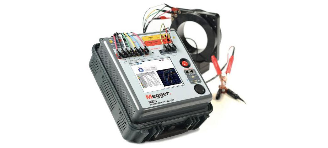
Current Transformer Test Equipment Example Photo: Megger
CT test sets are compact, multifunctional units designed to conduct demagnetization, ratio, saturation, winding resistance, polarity, phase deviation, and insulation tests on current transformers. High-end CT test equipment can directly connect to multi-ratio CTs and conduct all tests on all taps with the press of a button, without the need to change leads.
Current transformers can be tested in their equipment configuration, whether mounted in transformers, oil circuit breakers, or switchgear. Modern CTs with multiple voltage and current outputs can also function as a relay test set when operated with a laptop computer.
Related: 6 Electrical Tests for Current Transformers Explained
Magnetron Atmospheric Condition (MAC) Test Set
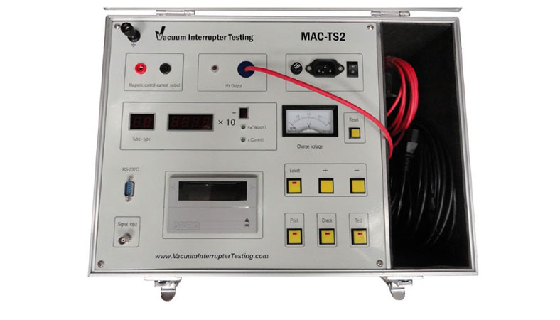
Magnetron Atmospheric Condition (MAC) Test Set Example. Photo: Vacuum Interrupter Testing
Traditional field testing of vacuum interrupters uses the high-potential (hi-pot) test to assess the dielectric strength of the bottle. This test produces a go/no-go result, which doesn’t determine when or if the gas pressure inside the bottle has dropped to a critical level. Unlike the hi-pot test, testing vacuum interrupters using magnetron atmospheric condition (MAC) principles can offer a viable way to assess the condition of vacuum interrupters before they fail.
The magnetic field test is set up by placing the vacuum interrupter into a field coil, which generates a constant DC current during the test. A continuous DC voltage, typically 10 kV, is applied to the open contacts, and the current flow through the vacuum interrupter is measured.
Related: Magnetron Atmospheric Condition (MAC) Testing Principles
Ground Resistance Test Set
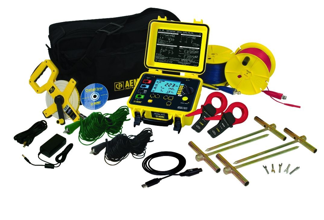
Ground Resistance Test Equipment with Accessories. Photo: AEMC
The ground resistance test set functions by injecting a current into the earth between a test electrode and a remote probe, measuring the voltage drop caused by the soil to a designated point, and then using Ohm’s Law to calculate the resistance.
Ground resistance test sets come in various styles, with the most common ones being the 4-terminal unit for soil resistivity testing and the 3-terminal unit for fall-of-potential testing. Copper rods or similar stakes are employed to establish contact with the earth, along with spools of small stranded wire to facilitate long-distance measurements.
Clamp-On Ground Resistance Testers measure ground rod and grid resistance without the need for auxiliary ground rods. They provide accurate readings without disconnecting the ground system under test, but they do have limitations.
Related: 4 Important Methods of Ground Resistance Testing
Power Recorder
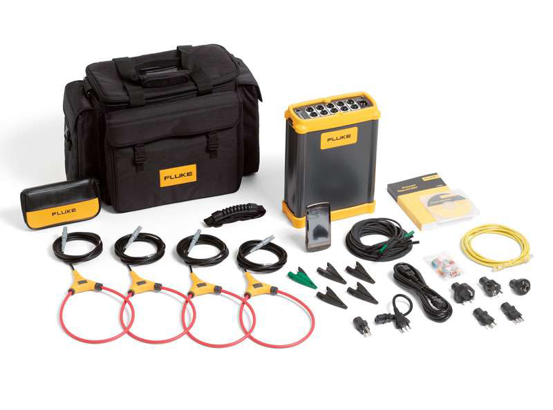
There are many different types of power recorder which range in size, accuracy and storage capability. Photo: Fluke
Power recorders are devices used to gather voltage and current data that can be downloaded into software for the analysis of electrical system conditions. These are troubleshooting tools employed to identify electrical issues such as voltage swells, sags, flicker, and poor power factor.
Power recorders can also be utilized to measure power consumption over a period of time, which is valuable for engineers planning system expansion or for customers looking to audit their energy bills. There are various types of power recorders available, varying in size, accuracy, and storage capacity.
Installation of a 3-phase power recorder involves wrapping conductors with split-core CT’s and clipping a set of leads to system voltage and ground. The recorder is set up to measure according to the system configuration for a specified time period and can also be viewed in real time using a PC or integrated screen.
Related: Power Quality Analysis: Basic Theory and Applications Explained
Infrared Camera
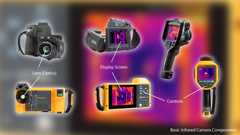
Infrared cameras are available in a variety of styles and resolutions. Which camera is best for an inspection depends on the type of equipment to be inspected and the environmental conditions. Photo: TestGuy
Thermal imagers are cameras that detect invisible infrared radiation and convert that data into a colored image on a screen. Infrared cameras are primarily used for inspecting the integrity of electrical systems because the testing procedures are non-contact and can be carried out swiftly, even while the equipment is in service.
Comparing the thermal signature of normally operating equipment to the one being assessed for abnormal conditions provides an excellent means of troubleshooting. Even if an abnormal thermal image is not fully understood, it can still be used to assess whether further testing may be necessary.
Thermal imagers are categorized based on their accuracy and detector resolution. High-end infrared cameras offer high-resolution image capture and temperature accuracy down to a tenth of a degree or less.
Related: Infrared Thermography for Electrical Distribution Systems
Vibration Tester
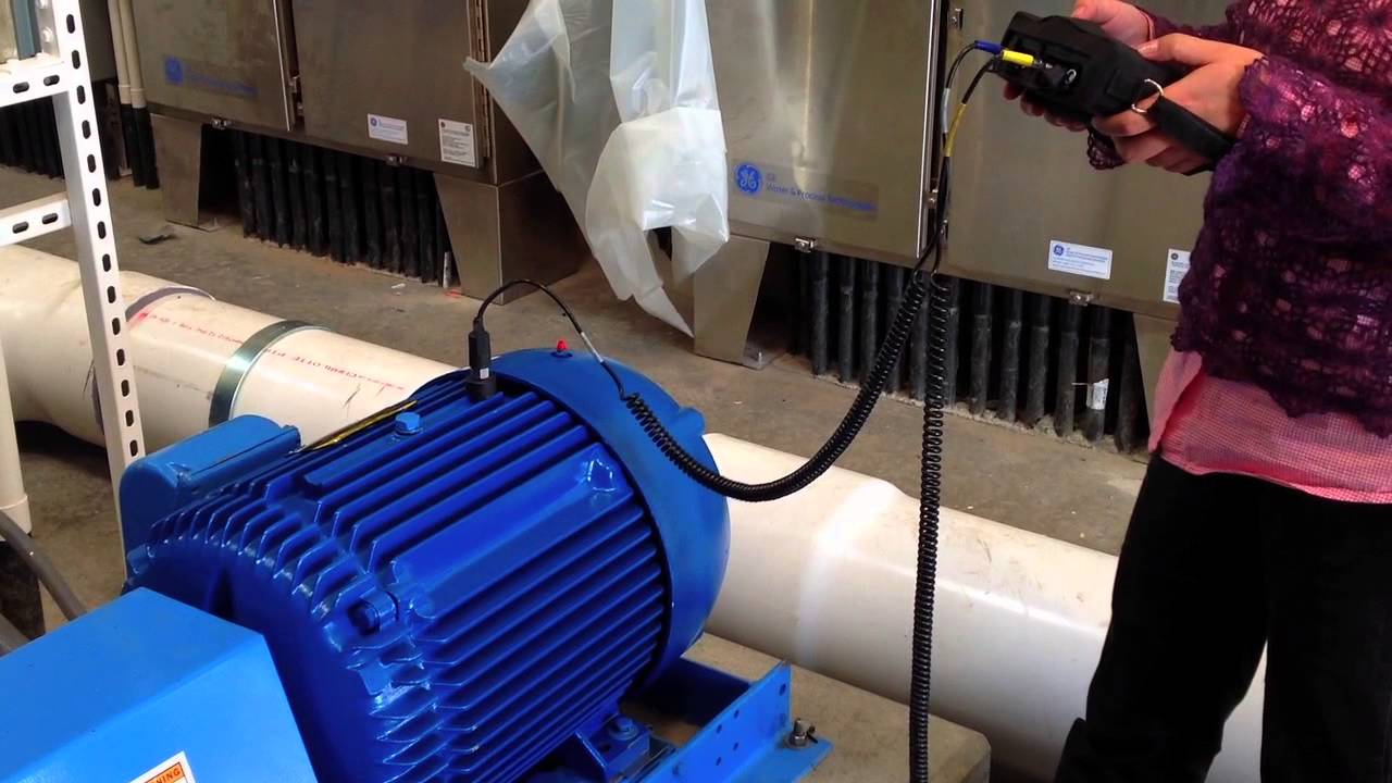
As the machine under test operates, the accelerometer detects its vibration along three planes of movement (vertical, horizontal and axial). Photo: BrithineeElectric
Vibration analyzers are used to identify and locate the most common mechanical faults (such as bearings, misalignment, unbalance, and looseness) in rotating machinery. When mechanical or electrical faults develop in motors, vibration levels increase. These increases in vibration and noise levels occur at varying degrees of severity as a fault develops.
Accelerometers are used to capture vibration measurements while the equipment is in operation, and the data is then imported into software for analysis. As the machine under test operates, the accelerometer detects its vibration along three planes of movement: vertical, horizontal, and axial.
Ultrasonic Tester
Arcing, tracking, and corona all result in ionization, which disrupts the surrounding air molecules. An ultrasonic tester detects high-frequency sounds produced by these emissions and converts them into the human audible range.
The sound of each emission is listened to using headphones, and the signal’s intensity is observed on a display panel. These sounds can be recorded and analyzed through ultrasound spectral analysis software for a more precise diagnosis.
Normally, electrical equipment should be silent, although some equipment, such as transformers, may produce a constant hum or steady mechanical noises. These sounds should not be confused with the erratic, sizzling, frying, uneven, and popping sounds of an electrical discharge.
Ultrasonic detectors are also valuable for detecting air leaks in transformer tanks and gas-insulated circuit breakers.
Load Bank
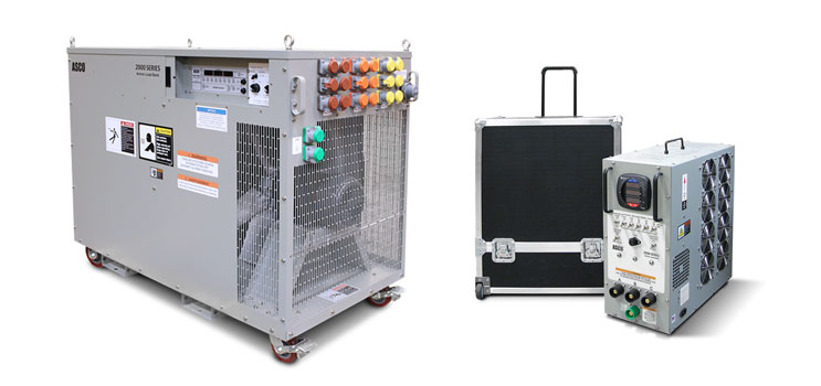
Load banks are available for a variety of applications and are usually sized by kW rating. Photo: ASCO Avtron
Load banks are utilized for commissioning, maintaining, and verifying electrical power sources, such as diesel generators and uninterruptible power supplies (UPS). The load bank applies an electrical load to the device under test and dissipates the resulting electrical energy through resistive elements as heat. These resistive elements are cooled with motorized fans within the load bank’s construction.
Multiple load banks can be interconnected if necessary. Some load banks are entirely resistive, while others may be purely inductive, purely capacitive, or a combination of the three. Load banks are the most effective way to simulate, confirm, and validate the real-life demands on critical power systems.
Battery Impedance Tester
Battery Impedance Test Equipment is primarily employed in substation and UPS applications to assess the condition of lead-acid cells by measuring important battery parameters such as cell impedance, cell voltage, inter-cell connection resistance, and ripple current. All three tests can be conducted with a single unit.
The battery impedance tester operates by applying an AC current signal across an individual cell and measuring the AC voltage drop caused by that current, as well as the current within the individual cell. It then calculates the impedance. The standard lead set used is a dual-point, Kelvin-style lead. One point is for applying the current, and the other is for measuring the potential.
Related: 3 Simple and Effective Tests for Battery Systems
Time-domain reflectometer
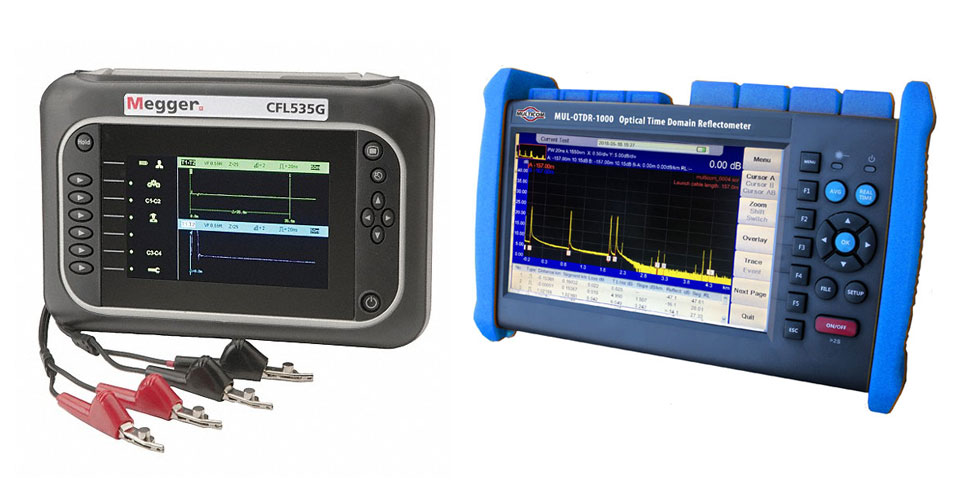
Electronic and Optical Time-Domain Reflectometer Test Equipment
The time-domain reflectometer (TDR) is used to determine the characteristics of electrical paths by transmitting a signal and observing reflected waveforms along a conductor. If the conductor is of a uniform impedance and is properly terminated, then there will be no reflections and the remaining incident signal will be absorbed at the far-end by the termination. If there are impedance variations, due to a fault or poor terminations, then some of the incident signal will be reflected back to the source. The operating principle of a TDR is similar to that of radar.
An optical time-domain reflectometer (OTDR) is the optical equivalent of an electronic time domain reflectometer (TDR). The OTDR injects a series of optical pulses into the optical fiber under test and extracts light that is scattered or reflected back from points along the fiber. The strength of the return pulses is measured and integrated as a function of time, and plotted as a function of length of the fiber. This is equivalent to the way that an electronic time-domain meter measures reflections caused by changes in the impedance of the cable under test.