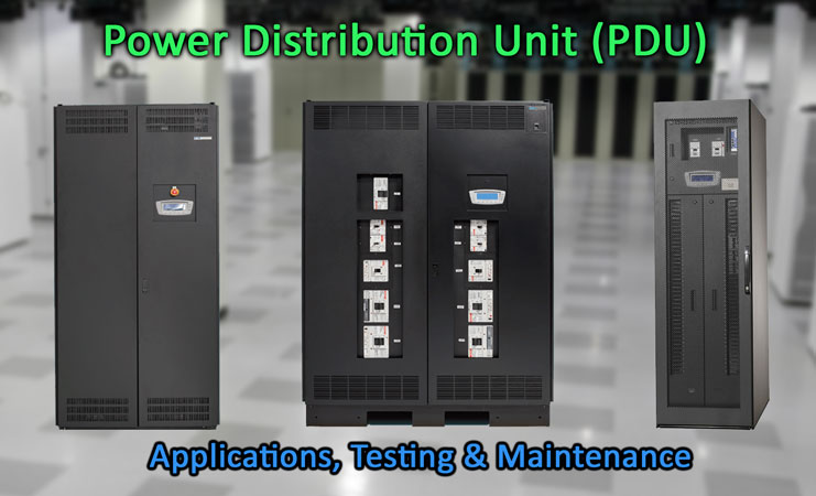
This guide covers the basics of pdu construction, applications, testing and maintenance procedures. Photo: TestGuy.
A power distribution unit (PDU) is a device designed to distribute electric power to servers, networking hardware, telecom equipment, and other devices located within a data center. It does not generate or condition power but delivers AC power from an uninterruptible power supply (UPS), a generator, or a utility power source.
Traditional data center power distribution designs consist of multiple PDUs delivering power to remote power panels (RPPs) throughout the building. These RPPs, in turn, deliver power to network hardware racks via power cabling routed underneath a raised floor, known as “whips.”
PDUs typically consist of a main input circuit breaker, an isolation output transformer, a monitoring/operation control panel, an integrated communication server, and a subfeed breaker system. The unit provides power distribution, voltage transformation, metering, status monitoring, and load profiling housed in a single, free-standing cabinet.
Power from the AC source is routed through the PDU main input breaker and the isolation output transformer to the distribution bus or cable. From here, power is delivered to subfeed breakers and then distributed to critical loads.
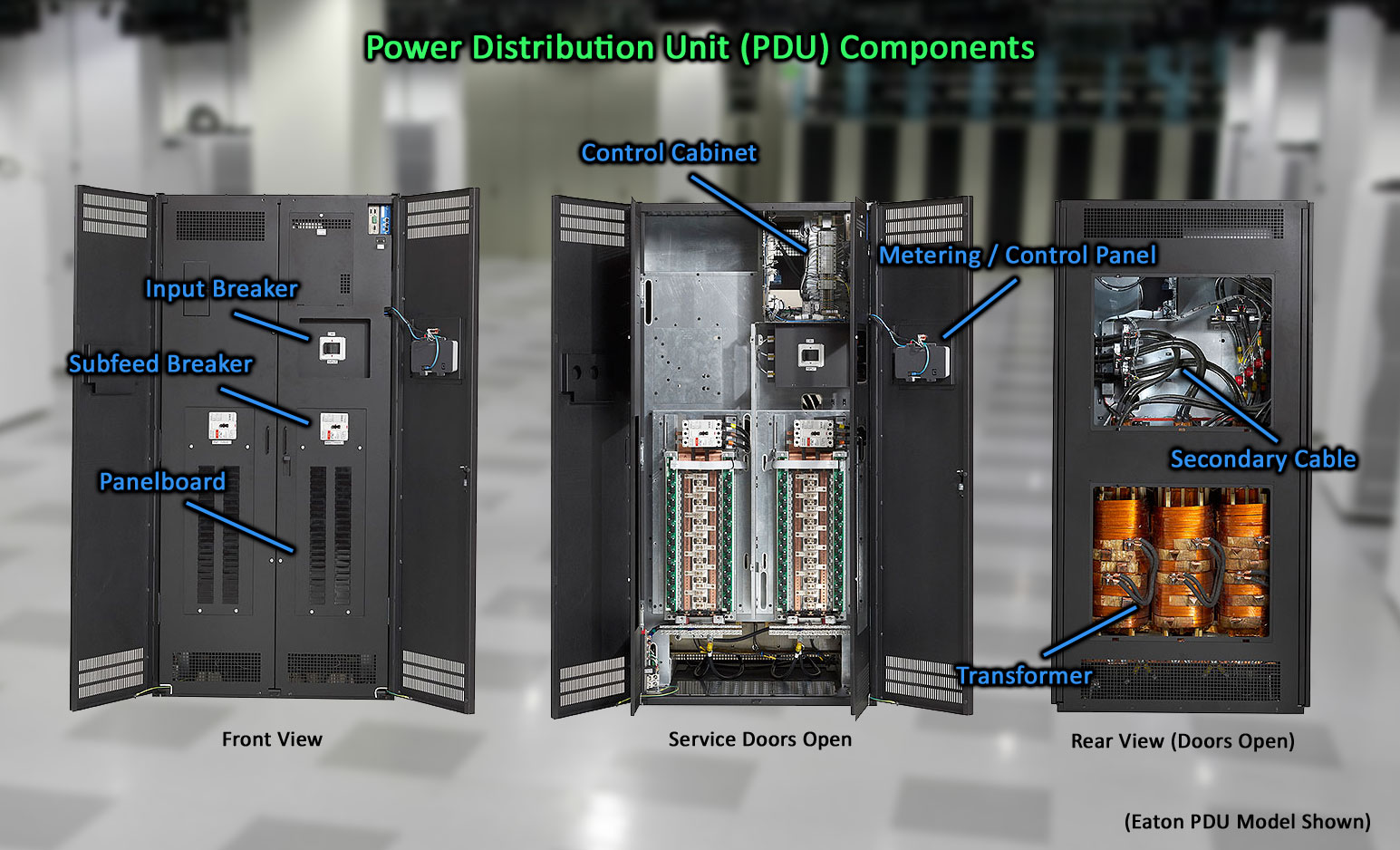
Power Distribution Units voltage transformation, metering, status monitoring, and load profiling housed in a single, free-standing cabinet. Photo: TestGuy
PDU Components
Main Input Breaker – The incoming power feed is connected to the main input breaker, when closed the isolation transformer will become energized, sending power to the subfeed breakers.
Output Transformer – PDU transformers are designed for efficient isolation and provide 208Vac power from a 380 Vac, 400 Vac, 415 Vac, 480Vac, or 600 Vac input. Copper-wound transformers increase performance and significantly reduce EMI and RFI noise. The typical operating range for a power distribution unit is anywhere from 50kVA up to 800kVA.
Subfeed Breakers – Depending on the style of PDU, the subfeed breaker system may consist of large MCCBs that feed smaller remote power panelboards, or the branch circuit panels may be integrated into the PDU enclosure itself.
Surge Suppression – Data center PDUs supply power to sensitive electronic components, which require protection from damaging transients, surges, and electrical line noise. This device is tapped off the subfeed bus and equipped with a circuit breaker for isolation during maintenance. Surge arresters may also be present on the primary side.
Metering – Integrated power meters at the PDU enclosure provide status and event information to operating personnel and building managers. Typical monitoring features include input/output voltage and current, kVA, kW, frequency, percent loading, and load profiling. Capacity and redundancy can be managed on every circuit.
Control Panel – PDU control panels are usually small touchscreen or push button displays that allow the user to change the unit configuration or view metering parameters.
Communication Module – Remote monitoring of the control panel or metering package interfaces to the building management system, utilizing network technologies such as Modbus and web server.
Infrared Ports – Optional inspection ports may be installed on a PDU enclosure for easy transformer tap and terminal inspections using IR temperature measuring equipment.
Related: Infrared Thermography for Electrical Distribution Systems
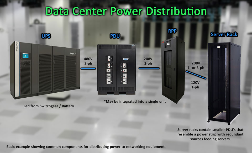
Data Center Electrical Power Distribution Simplified Example. Photo: TestGuy
PDU Operation
Power Distribution Units generally require very little in terms of an operating sequence. Closing the main input breaker will typically energize the transformer and subsequent subfeeders. Additional startup steps may be required through the control panel if equipped.
Optional shunt trip terminals can be used to easily connect subfeed breakers to emergency off devices. Auxiliary contact connections can also be provided to allow monitoring of the breaker open or closed status.
Related: Circuit Breaker Accessories Explained
Testing & Maintenance
Acceptance testing should be performed on all new installations prior to energizing. Each component of the PDU is individually inspected and electrically tested to ensure reliability and safety before startup.
Once in service, periodic inspections of the PDU should be made to determine if components, wiring, and connections exhibit evidence of overheating. Particular attention should be given to bolted connections to ensure efficient current paths.
Related: Fastener Torque in Electrical Systems: Understanding the Basics of Mechanical Connections
A brief overview of common electrical tests for each component is listed below. Which tests are performed on each PDU component is to be determined by the equipment owner and individual project specifications.
Circuit Breakers (MCCB)
- Primary/Secondary injection of trip unit – which is better?
- Contact-resistance
- Insulation-resistance
Isolation Transformer
PDU Bus
- Connection resistance and insulation-resistance
Grounding
- 2-point continuity check to local grid
Metering
- Voltage/Current injection at secondary level to verify the meter reads within its specified error
Instrument transformers
- Voltage transformers, control power transformers, and current transformers are voltage/current injected and tested for insulation-resistance.
Surge Arresters
- Insulation resistance
- Grounding connection resistance
Operational Checks
- System function tests prove the correct interaction of all sensing, processing, and action devices. Consult the manufacturers literature for the specific device under test for the correct operational checks procedure.
Other Considerations
The tests above are performed in addition to a thorough visual/mechanical inspection and cleaning of the unit periodically. All tests should be conducted with equipment de-energized by a qualified testing agency utilizing certified test technicians.
Related: Cleaning Methods for Electrical Preventive Maintenance