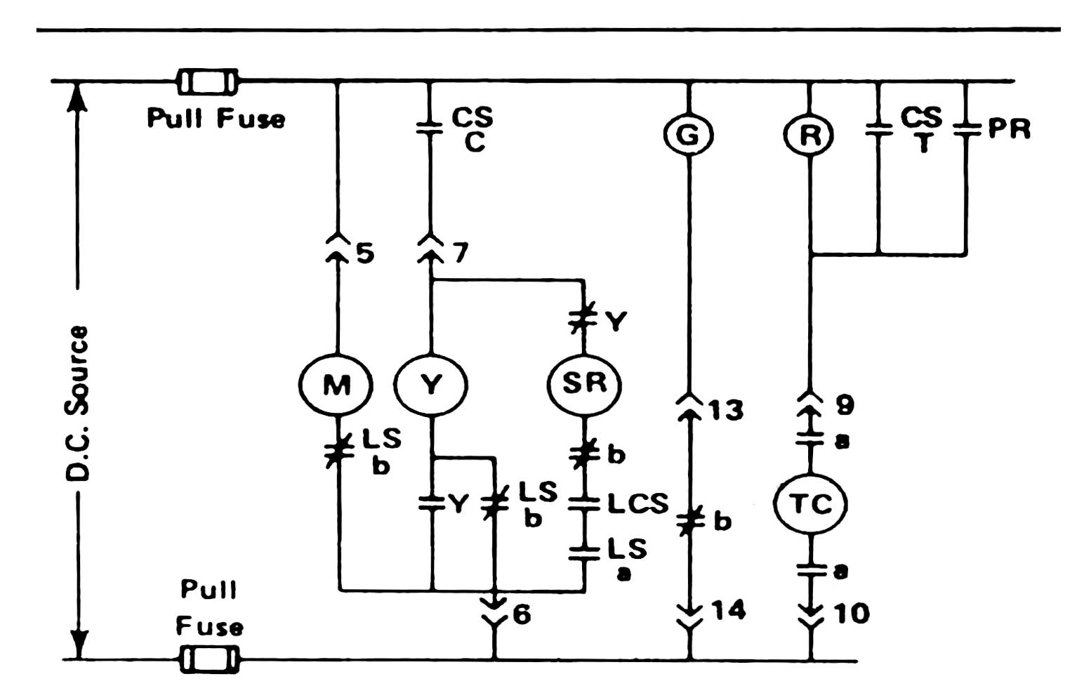
A typical wiring diagram with DC control for a Westinghouse DHP is shown in the figure below. We will use this simple diagram to discuss the components involved in the electrical operating sequence of a circuit breaker.
Medium Voltage Circuit Breaker Control Circuit. Photo: Westinghouse DHP.
(>> #) Secondary Disconnect
Control voltage for electrical operation is supplied to the circuit breaker through the secondary disconnect. The secondary disconnect also serves as the interface for the auxiliary contacts on the circuit breaker to the associated switchboard and provides indication to the control system about the breaker’s position.
(CS) Control Switch
Usually located on the cubicle door or at a remote control panel, the control switch is employed for the manual operation of a circuit breaker through electrical control. CSC = Close contact. CST = Trip contact.
(PR) Protective Relay
The primary purpose of the protective relay is to minimize damage to equipment and prevent interruptions to power systems when electrical failures occur. Instrument transformers assist the relaying equipment in this task by sensing abnormal power conditions.
(TC) Trip Coil
The trip coil is a simple solenoid that operates the circuit breaker trip latch.
(Y) Anti-Pump Relay
Locks out the control circuit if the close operation is not completed. If the breaker fails to close on the first attempt, and the close coil remains energized, the “Y Relay” initiates a lockout to prevent the breaker from attempting another close.
If the close signal is initiated but not removed, the breaker has the potential to cycle through an endless close, trip, charge, close, and trip cycle (Pumping). The Y coil opens the Y contact in the close circuit, and as long as the close signal is present, the circuit breaker cannot re-close.
(SR) Spring Release
The close coil is a solenoid that operates the circuit breaker close latch, allowing for remote closing operations.
(M) Spring Charging Motor
Automatically charges the spring mechanism for closing the circuit breaker and recharges the spring mechanism when the circuit breaker is in the ON position, enabling instantaneous re-closing of the circuit breaker following an open operation. The charging motor is energized automatically when the circuit breaker is racked in.
(Lsb) Motor Cutoff Switch
Usually operated by a timing cam, this switch opens the normally closed contacts and de-energizes the motor when the breaker is charged. It may also include a set of normally open contacts that close and complete the circuit to the close coil.
(LC) Latch Check Switch
A mechanically-operated switch which senses if the trip latch is reset. Indicates when the breaker is “ready to close.”
(G) Green Indicating Light
When the breaker opens the green lamp illuminates – the circuit is complete with 52b contact switching from open to close.
(R) Red Indicating Light
When the breaker is closed and energized, the red lamp illuminates to indicate a live breaker. The trip circuit is “armed,” and once a control switch or protective relay contact is operated, the breaker will open.
( | | |/| ) Auxiliary Switch
The contacts of the auxiliary switch are designed to open or close external control circuits as the breaker operates. The circuit breaker operating mechanism controls the opening or closing of the switches.
As the mechanism rises to the “open” position (breaker tripping), the switch is forced to “make” or “break” contacts. When the mechanism is pulled closed (breaker ON), the switch resets and returns the contacts to their deactivated position.
( | | ) Auxiliary Switch Contact (a)
The aux switch contacts, known as “a contacts,” are open when the breaker is open. These contacts are in the same position as the breaker main contacts.
( |/| ) Auxiliary Switch Contact (b)
The aux switch contacts, closed when the breaker is open, are referred to as “b contacts.” These contacts are in the opposite position compared to the breaker main contacts.