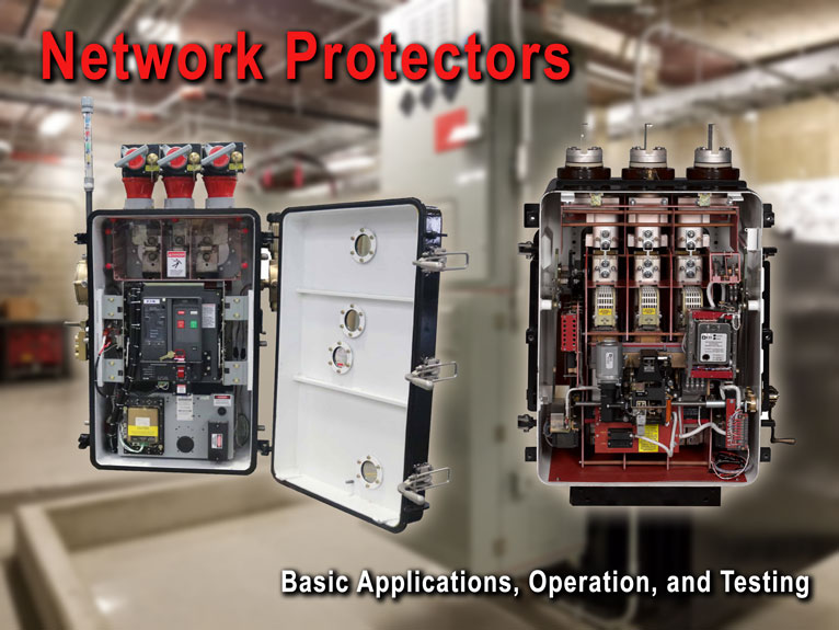
This guide covers network protector basic operation and maintenance procedures. Photo: TestGuy.
Network systems are commonly used in hospitals, high rise office buildings, and institutional facilities where a high degree of service reliability is required. In the network system arrangement, several utility services are paralleled at the transformer secondaries, creating a system that is dependable and versatile.
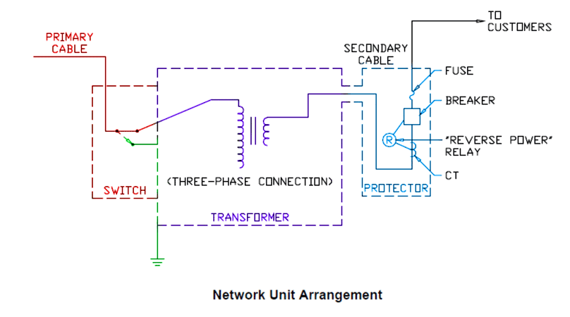
Distribution networks often utilize two or more transformers supplied from different high-voltage feeders. The transformers are connected through network protectors to a common collector bar, and the load is served by cables or buses off the collector bus.
The most important elements of an AC network power system are the network transformer and the network protector. These devices provide for automatic operation to reliably serve loads, isolate faults, and distribute power uniformly across the multiple primary circuits.
Important Network Terms
Secondary networks serve high-density loads, such as downtown districts, with multiple primary feeders. Secondaries are tied in a grid pattern for reliability, and the most common grid voltage is 216/125 volts.
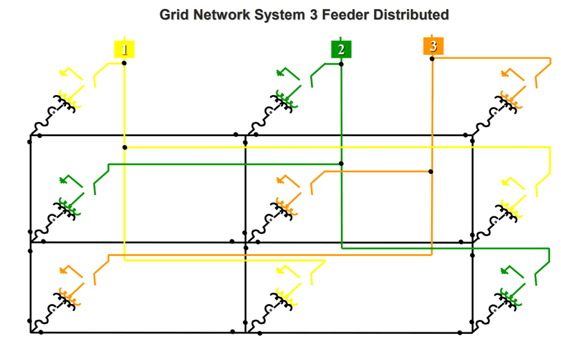
3 Feeder Grid Network Electrical Distribution System Example. Photo: EATON
Spot networks refer to a single location, such as a large institutional building, with a transformer and network protector adjacent to a particular load. Spot networks have a voltage of 480/277 volts.
Related: 10 Electrical Distribution System Arrangements Explained
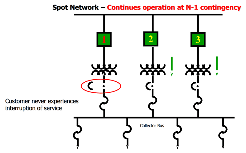
Spot Network Electrical Distribution System Example. Photo: EATON
Contents
- Network Transformers
- Network Protectors
- NWP Relay Protection
- Cable Limiters
- Current Limiting Fuses
- Network Protector Testing and Maintenance
1. Network Transformers
Special distribution transformers are employed in network systems that are constructed with unique requirements for the application, such as ventilation, physical size, submersibility, and short-circuit ratings. Network transformers are typically available in sizes up to 2500 kVA, with the most common size being 500 kVA.
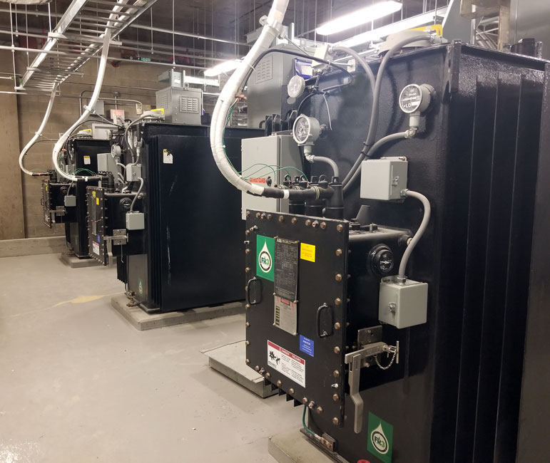
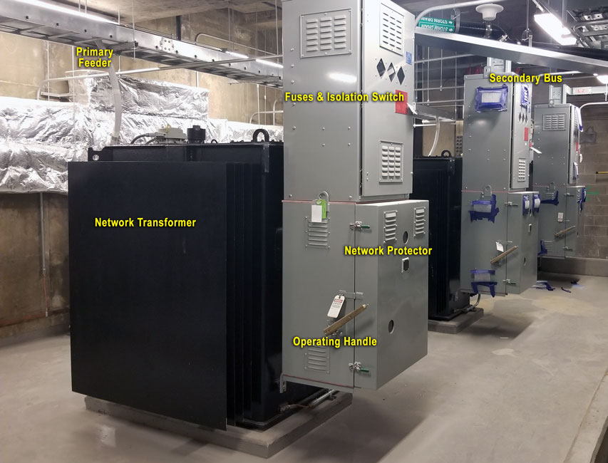
Spot Network Transformers. Photo: TestGuy.
Network transformers are manufactured in several designs for installation in underground vaults, pad-mounted locations, or inside buildings. They are usually oil-filled or may use a biodegradable or synthetic non-flammable liquid for the insulating and cooling medium.
An internal disconnect switch is provided to isolate the transformer for maintenance or inspection and may also be used to ground the primary cable when work is being performed on the unit. Network transformer disconnect switches are manually operated and typically include an interlock to prevent improper operation with the circuit energized.
Network transformers are manufactured in several designs for installation in underground vaults, pad mounted or inside buildings. Photo: Richards Mfg.
Network systems may serve an area with a kVA demand as high as 40,000 kVA. In New York City, individual networks may supply even larger loads, in some cases as great as 250,000 kVA.
2. Network Protectors
A network protector (NWP) is connected between the secondary terminals of the network transformer and the secondary network system. This unit connects the power supply (network transformer) to the load (network system) and disconnects these elements when their roles become reversed.
Most faults can be cleared without interrupting service to any load on the collector bus. Think of network protectors as specially designed circuit breakers used to isolate transformer faults that are back-fed through the low voltage system.
A network protector (NWP) is connected between the secondary terminals of the network transformer and the secondary network system. Photo: EATON
The network protector consists of a low-voltage air circuit breaker and associated protective relaying as an integrated unit. Power fuses may be included for additional protection and sized for primary faults, which are not isolated by the network protector breaker.
Primary Fault Protection
The purpose of the network protector is to automatically isolate the network when a fault occurs on the primary system. For example, during a primary feeder fault, the circuit breaker located upstream will operate to open the primary feeder, and both transformers connected to the faulted feeder will then be backfed by the secondary network.
The NWP relay will sense this as a reverse power condition and automatically trip open the network protector to isolate the fault. Service to all loads will continue uninterrupted, being supplied by the remaining four transformers and the grid system.
The network protector consists of a transformer, low voltage air circuit breaker and associated protective relaying as an integrated unit. Photo: TestGuy
The network protector, located on the transformer secondary, is designed to protect the system from primary feeder faults or internal transformer faults. The protector is not designed to operate for secondary faults.
Overload Capacity
Network transformers must be designed to handle overloads caused by such events and sized to carry additional capacity when other transformers in the network are removed. A fault within the network protector or in the secondary winding of the transformer is the most damaging type of fault in terms of network protector operation.
A secondary system fault will be cleared by secondary fuses, secondary cable limiters, or by the cable itself. Primary feeder breakers will not trip, nor will network protectors trip when a secondary fault occurs.
Enclosure Design
Network protectors are available in submersible or non-submersible (ventilated) enclosures. The submersible enclosure provides protection against flooding and water damage to its enclosed mechanism.
The non-submersible enclosure is a dust-proof steel casing that provides the enclosed mechanism protection from dust and dirt. Both styles of protector are bolted directly to the network transformer tank. In some situations, a network protector may be mounted on a wall in the vault or located on a separate frame in the vault.
Operating Positions
The network protector has an operating handle with three operating positions: “automatic,” “open,” and “closed”. The automatic position can be considered as the normal handle position, as it allows the relays to control the protector’s operation.
It is not recommended that a Network Protector be placed into service by utilizing the external handle CLOSE mode. The protector should be placed in the AUTO position to permit the protective relay to control the breaker actions.
3. NWP Relay Protection
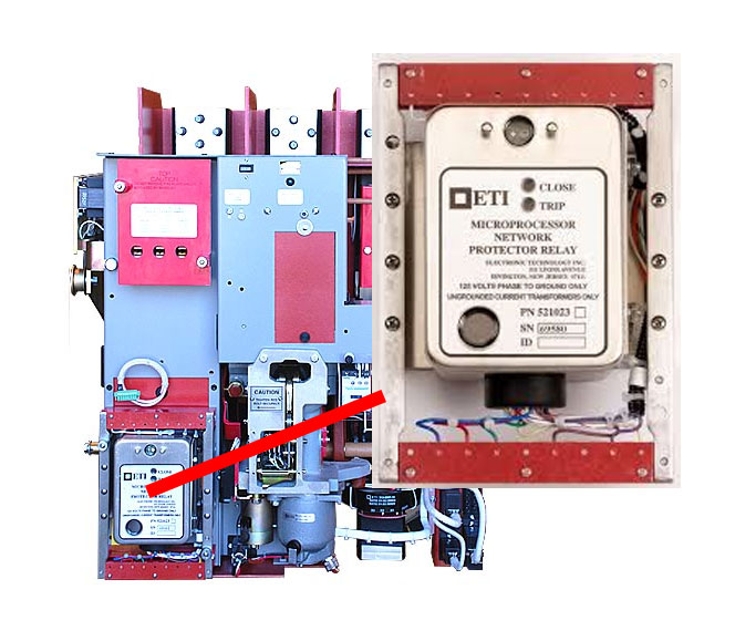
The NWP relay will sense a reverse power condition and automatically trip open the network protector to isolate the fault. Photo: Richards/ETI
Network protectors can be viewed as a 2-position secondary switch with the ability to recognize the direction of power flow through it. The network protector will automatically open when the network system load decreases and automatically close when the network load increases by means of relays.
Operating Principle
The relay system has two primary functions. One is to trip the circuit, and the other is to re-close the circuit. The tripping circuit senses current being fed from the network to its feeders. If the relay detects current flowing from the network into the transformer, it will open the network protector.
The re-closing circuit (or master relay) monitors the transformer output voltage and compares that to the network system voltage.
-
If the network system voltage is greater than the transformer’s output voltage, the re-close circuit does not operate.
-
If the voltage in the network system is lower than the transformer output voltage, the re-closing circuit will operate and close the network transformer into the common load.
Protection Settings
The voltage difference between the transformer and network is commonly set anywhere between 1 and 3 volts. When the relay sees this predetermined voltage difference, it will either re-close or open the protector.
In some particular relay schemes, the voltage and current must also be in phase for this operation to take place. The phasing relay looks at when the network’s transformer voltage leads the network voltage by a specified amount. Its purpose is to ensure a re-close operation only when both the voltage comparison and phase comparison are within their specified ranges.
4. Cable Limiters
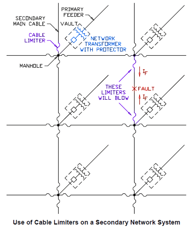
In order to provide secondary protection on higher voltage network systems, the utility company will typically install devices known as cable limiters. These devices consist of a copper tube with an element of reduced cross-section, designed to operate similarly to a fuse.
The limiter element is enclosed in a special housing and inserted into each end of the secondary main cables. The cable limiter is sized to blow for cable faults within the particular section of the secondary network it protects.
It’s important to note that a cable limiter is not the same thing as a current limiting fuse. Photo: Richards Mfg.
The use of cable limiters on the secondary network is shown in the figure above. The two limiters protecting the faulted section will blow to isolate the fault. Note that all the adjacent cable limiters will “see” a much smaller level of current and will not operate.
Cable limiters operate quickly enough to prevent damage to the cable insulation. A large enough fault will cause the limiter to blow well before any damage can be done to the cable insulation.
The term “limiters” comes from their ability to limit damage due to a fault. A limiter can be thought of as a sacrificial element to prevent widespread damage to other equipment.
5. Current Limiting Fuses
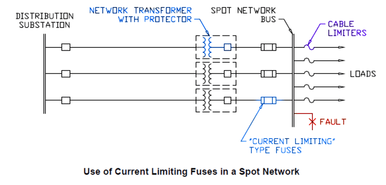
Power fuses may also be installed alongside network protectors. In this type of application, the current-limiting fuse would be sized to blow for high-magnitude secondary bus faults.
Current-limiting fuses act very quickly and will actually limit the magnitude of fault current allowed to flow. It’s important to note that a cable limiter is not the same thing as a current-limiting fuse.
Spot Network Secondary Protection. Photo: Richards Mfg.
For the bus fault example shown in the figure above, all three limiting fuses would blow, protecting the system from damage.
6. Network Protector Testing and Maintenance
Before placing a network protector into service, it should be tested. Maintenance inspections and routine tests are conducted throughout the year, depending on the operating environment and service reliability requirements.
Network transformers deserve the same treatment when it comes to testing and maintenance; however, for the purposes of this article, the testing section will focus only on the network protector unit itself.
Related: Transformer Diagnostics and Condition Assessment
WARNING: Testing network protectors involves working with live high voltage systems which can cause serious injury or death. Only trained and qualified testing personnel should conduct field maintenance, the information presented in this guide is for reference only.
Visual/Mechanical Inspections
General inspection procedures for network protectors include an evaluation of the overall physical and mechanical condition of the unit. Nameplate data should be compared to project drawings and specifications during acceptance testing.
Inspect the network protector installation, including anchorage, alignment, and grounding. Verify that the unit is clean and that the arc chutes are intact.
Related: Cleaning Methods for Electrical Preventive Maintenance
Moving and stationary contacts should be inspected for condition and alignment. Primary and secondary contact wipe and other dimensions vital to the satisfactory operation of the network protector should be verified as correct.
Mechanical operator and contact alignment tests should be performed on both the network protector and its operating mechanism. Bolted electrical connections should be inspected for high resistance using a low-resistance ohmmeter (DLRO), IR camera, or calibrated torque wrench.
Related: Fastener Torque in Electrical Systems: Understanding the Basics of Mechanical Connections
Inspect the network protector cell fit and alignment. The racking mechanism operation should be smooth and easy to engage, verify appropriate lubrication on moving current-carrying parts, and on moving and sliding surfaces.
Related: 3 Critical Lubrication Points for Power Circuit Breakers
Submersible enclosures should be tested for leaks using techniques recommended by the unit manufacturer. The operations counter should advance one digit per close-open cycle, and readings should be recorded as found and as left after testing.
Electrical Tests
Perform a contact/pole-resistance test and inspect other bolted electrical connections using a DLRO where applicable. In most cases, a 10A test current is sufficient. Measure the resistance of each power fuse.
Investigate values that deviate from those of similar bolted connections by more than 50 percent of the lowest value. Investigate fuse resistance that deviates by more than 15 percent.
Insulation-resistance tests are performed for one minute on each pole, phase-to-phase, and phase-to-ground with the network protector closed, and across each open pole. Voltage should be applied using values found in the manufacturer’s literature or use NETA Table 100.1 as a substitute.
Related: Insulation Resistance Test Methods, A Beginners Guide
Insulation-resistance tests are optional on all control wiring with respect to ground. NETA standards call for the applied potential to be 500 volts DC for 300-volt rated cable and 1000 volts DC for 600-volt rated cable. The test duration is for one minute; investigate values less than two megohms.
For units with solid-state components, follow manufacturer’s recommendation as test voltage can damage these components.
NWP Relay and Control Tests
As a prerequisite to protective relay tests, any associated voltage and/or current transformer ratios and polarities should be verified as correct.
-
Re-close voltage – With the network protector open and in auto, record the voltage at which the network protector closes at +60 degrees (this is the lead voltage). Repeat the test at -60 degrees (this is the lag voltage) and 0 degrees (master relay setting).
-
Reverse current – With the network protector closed and in auto, record the current at which the network protector opens. The current reading obtained is the reverse current setting of the master relay.
Related: Protective Relay Testing and Maintenance Overview
Verify that the motor can charge the closing mechanism at the minimum voltage specified by the unit manufacturer. The minimum operating voltage of the motor on the closing mechanism should be 75 percent or less of the rated control circuit voltage.
The minimum pickup voltage of the motor control relay should be within the unit manufacturer’s specifications, but not more than 75 percent of the rated control circuit voltage per NETA standards.
Verify the minimum pickup voltage of the trip actuator, and test the actuator reset for functionality. The trip actuator’s minimum pickup voltage should not exceed 75 percent of the rated control circuit voltage per NETA standards.
References
- GE Type MG-8 and MG-9 Network Protectors
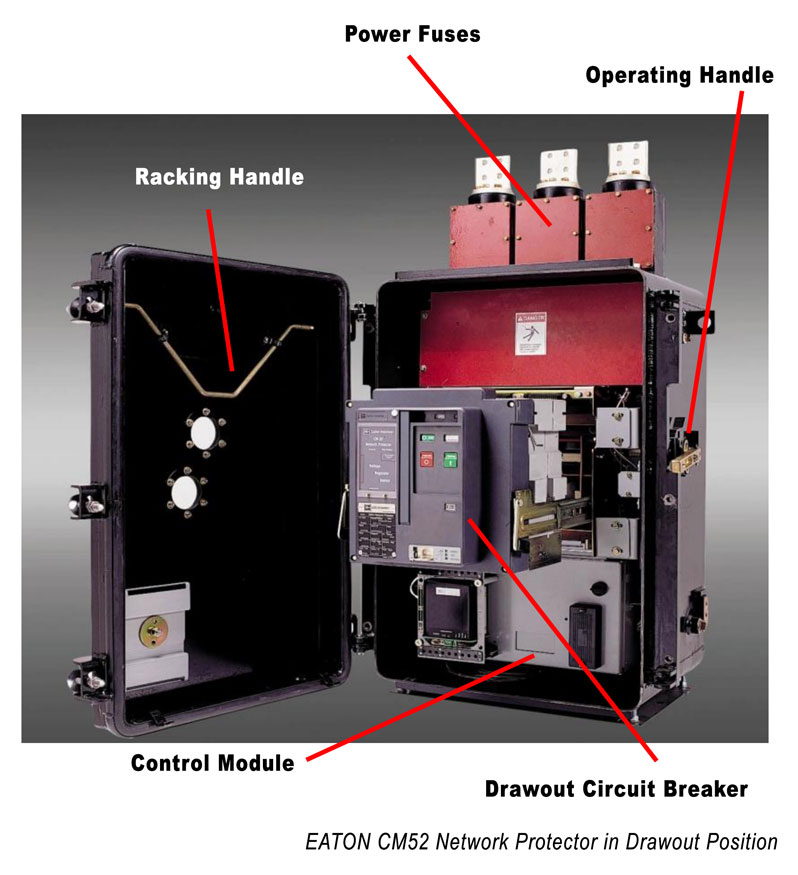
- EATON CM52 Network Protectors
- ETI MODEL 616001 AUTOMATIC NETWORK PROTECTOR RELAY TEST BOX
- NETA ATS-2017 Standard for Acceptance Testing Specifications for Electrical Power Equipment and Systems, 2017 Edition
- Electrical Power Equipment Maintenance and Testing
- Designing For a Critical Load using a Spot Network
- Richards NWP Training Manual