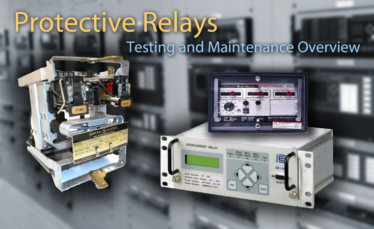
This guide provides a comprehensive overview of inspection and test procedures for protective relays in electrical power systems. Photo: TestGuy.
Protective relays are extensively utilized throughout the power system to promptly remove any element from service experiencing a short circuit, operating abnormally, or posing a risk to system operation. Instrument transformers support the relaying equipment in this task by sensing power conditions, while circuit breakers, responsive to signals from the relaying equipment, are capable of disconnecting the faulty element.
Due to their critical role in the power system, protective relays should undergo acceptance testing before being placed in service and periodic testing thereafter to ensure reliable performance. In a typical industrial application, testing should be conducted at least every 2 years in accordance with NFPA 70B.
Protective relay testing may be divided into three categories: acceptance testing, commissioning, and maintenance testing. The selection of specific testing procedures depends on project requirements and industry standards.
Ultimately, the determination of testing specifics lies with the equipment owner or system engineer, who must consider the unique characteristics of the equipment and industry nuances.
Contents
- Visual and Mechanical Inspection
- Verify Protective Settings
- Insulation Resistance Tests
- Additional Electrical Tests
- Targets and Indicators
- Protection Element Tests
- System Functional Tests
1. Visual and Mechanical Inspection
Testing and maintenance of protective relays always begin with a comprehensive visual and mechanical inspection. If the circuit to be tested is in service, one relay at a time should be removed (if applicable) to avoid completely disabling the protection.
What to check varies depending on the type of relay—whether electromechanical, solid-state, or microprocessor-based. Procedures for each type of relay are summarized below:
Inspections and Checks for Electromechanical and Solid State Relays
Electromechanical relays consist of physical moving parts to connect a contact within the output component of the relay. The movement of the contact is generated using electromagnetic forces from a low-power input signal.
Solid-state relays use power semiconductor devices such as thyristors and transistors to switch currents up to around a hundred amperes. Solid-state relays have fast switching speeds compared to electromechanical relays and have no physical contacts to wear out.
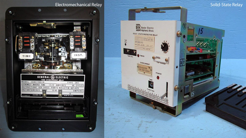
Examples of Electromechanical and Solid-State Protective Relays.
-
Record and compare the relay nameplate data with the applicable project drawings and specifications to ensure the correct equipment with the appropriate options are installed.
-
Inspect the relay and case for physical damage and verify that the entire unit is clean. For new installations, be sure that all shipping restraint material has been removed.
-
Tighten the relay case connections and inspect the cover for correct gasket seal. Inspect shorting hardware, connection paddles, and/or knife switches.
-
Inspect the relay unit for foreign material, particularly in disk slots of the damping and electromagnets. Remove any foreign material from the case and ensure the cover glass is clean.
-
Verify target reset functionality, disk clearance, contact clearance and spring bias.
-
Inspect spiral spring convolutions. The relay spiral spring should be concentric and should not show signs of overheating. The disk and contacts should be inspected for freedom of movement and correct travel.
-
Bearings and pivots should be clean and demonstrate fluid movement. Verify the tightness of all relay mounting hardware and connections. Delicately clean the fine silver contacts using a flexible burnishing tool that resembles a superfine file.
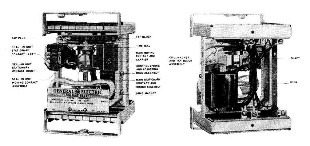
Electromechanical relay removed from case with components labeled. GE Type IAV54E Undervoltage Relay. Photo: General Electric.
Inspections and Checks for Microprocessor-Based Relays
Microprocessor relays are computer-based systems that utilize software-based protection algorithms for the detection of electrical faults. Digital relays serve as functional replacements for electro-mechanical protective relays and may encompass numerous protection functions in a single unit, in addition to providing metering, communication, and self-test functions.
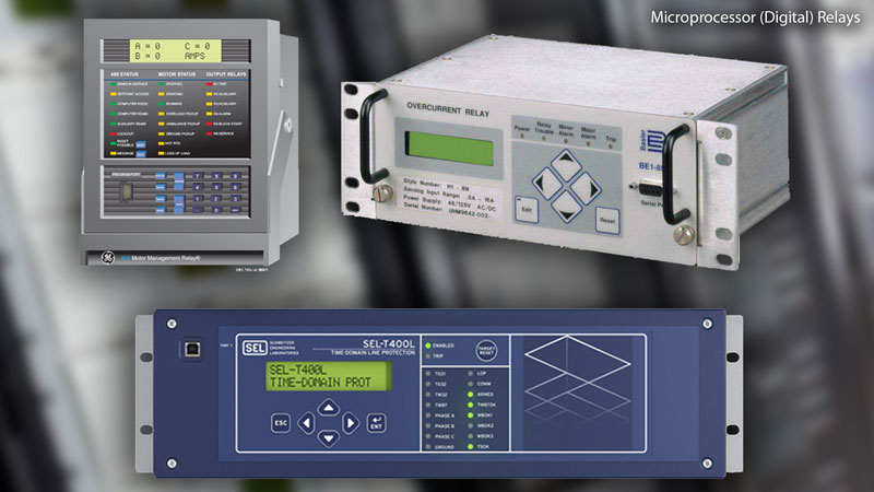
Example of Microprocessor-Based (Digital) Relays
-
The relay front panel should be clean and case free of foreign materials. Check for loose mounting hardware and electrical connections. Verify that the relay frame is grounded as specified in the manufacturers installation instructions.
-
Record important nameplate information such as the relay model number, style number, serial number, firmware revision, software revision, and rated control voltage.
-
All events from the event recorder should be downloaded in filtered and unfiltered mode before performing any tests on the relay. Download the sequence of events, maintenance data, and statistical data. Record passwords for all access levels for future reference.
-
Settings and logic files should be downloaded from the relay and settings compared to those specified in the coordination study or setting sheet supplied by owner. Set the relay in accordance with the engineered setting file and coordination study.
-
Verify that the relay is showing the correct date and time. Compare the relay display time to actual time and record the difference. Set the relay clock if it’s not controlled externally. Connect backup battery.
-
Check with setting engineer or owner for applicable firmware updates and product recalls. Inspect, clean, and verify operation of shorting devices. Verify the operation of any light-emitting diodes, displays, and targets.
2. Verify Protective Settings
The as-left relay settings should align with the latest coordination and arc-flash study or engineered setting files. Verify that all settings are in accordance with the most recent protective device coordination study or setting sheet provided by the equipment owner. This information is often presented on a time–current curve of the coordination study, illustrating the characteristics of the relay.
Related: Electrical Power System Studies Explained
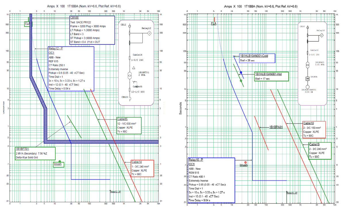
Example of protective relay coordination study settings characteristic curves. Photo: Indian Journal of Science and Technology.
3. Insulation Resistance Tests
Perform insulation-resistance tests on each electromechanical relay circuit-to-frame and ground. Procedures for conducting insulation-resistance tests on solid-state and microprocessor relays should be determined from the relay instruction manual. Some relay manufacturers may not recommend high-voltage insulation tests.
Related: Insulation Resistance Test Methods, A Beginners Guide
4. Additional Electrical Tests
Apply voltage or current to all microprocessor-based relay analog inputs and verify correct registration of the relay meter functions and verify SCADA metering values at remote terminals.
5. Targets and Indicators
For electromechanical and solid state relays, determine pickup and dropout of electromechanical targets. Verify operation of all light-emitting diode indicators and set the contrast for liquid-crystal display readouts.
6. Protection Element Tests
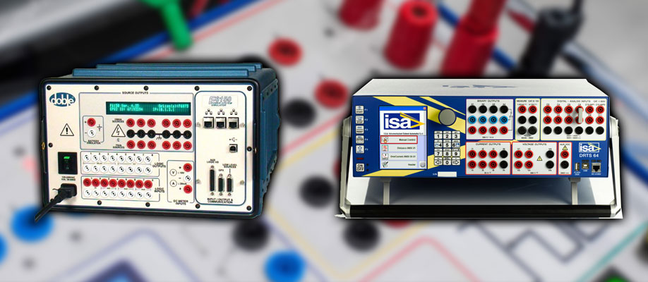
Relay test sets are fitted with multiple sources to test solid-state and multi-function numerical protection. Photo: TestGuy
Check functional operation of each element used in the protection scheme as described in the reference guide linked below. When not otherwise specified, use manufacturer’s recommended tolerances.
Attached Reference: Protective Relay Protection Element Tests
Operation of protection elements for devices listed in the attached reference should be calibrated using the manufacturer’s recommended tolerances unless critical test points are specified by the setting engineer. When critical test points are specified, the relay should be calibrated to those points even though other test points may be out of tolerance.
Under normal operating conditions, microprocessor-based relay operating characteristics do not change over time. Operating times are affected only by the relay settings and applied signals. It is not mandatory, per NETA standards, to verify operating characteristics as part of maintenance checks.
7. System Functional Tests
In addition to the inspection and testing of protective relays, it may be desirable to confirm the correct interaction of all sensing, processing, and action devices as a complete unit through system functional tests.

System functional tests prove the correct interaction of all sensing, processing, and action devices as a complete unit. Photo: Twins Chip Electrical Industry.
When conducting system functional tests, verify all interlock safety devices for fail-safe functions in addition to their individual design function. Confirm the correct operation of all sensing devices, alarms, and indicating devices.
Test lock-out relay and block close circuits, along with relay self-test, power supply failure, and trip coil monitor alarms back to SCADA. Verify the functionality of bus restoration and/or transfer switches.
Metering on protective relays and meters should be checked against a calibrated source. Verify that communication lines are operational for local and remote devices, and ensure that control annunciation systems are free of alarms. Investigate any alarms present.
Upon completion of testing, restore control circuits and current transfer circuits to normal operation. Verify that all systems are left in normal operating mode or position, ensure transfer and restoration schemes are enabled, and confirm that monitoring and protection devices are operational.
Electromechanical and Solid State Relay Functional Tests
Verify that each of the relay contacts performs its intended function in the control scheme, including:
- Breaker trip
- Close inhibit
- 86 lockout
- Alarm functions
Microprocessor-Based Relay Functional Tests
-
Check the operation of all active relay digital inputs and all output contacts or SCRs, preferably by operating the controlled device (circuit breaker, auxiliary relay, or alarm). Verify the functionality of all internal logic functions used in the protection scheme.
-
For pilot relay schemes, perform a loop-back test to check the receive and transmit communication circuits. All other relay communication links should be verified as operational.
-
Verify communication assisted protection schemes via end-to-end testing. Measure latency of communication lines for pilot wire, line differential and transfer trip protection schemes.
-
Reset all min/max records and fault counters at completion of testing to remove irrelevant data. Delete sequence-of-events records and all event records.
-
Verify trip and close coil monitoring functions. Verify relay SCADA communication and indications such as setting change, protection operate, protection fail, communication fail, fault recorder trigger.
References
- NFPA 70B: Recommended Practice for Electrical Equipment Maintenance, 2016 Edition
- NETA ATS-2017 Standard for Acceptance Testing Specifications for Electrical Power Equipment and Systems, 2017 Edition
- NETA MTS-2015 Standard for Maintenance Testing Specifications for Electrical Power Equipment and Systems, 2015 Edition