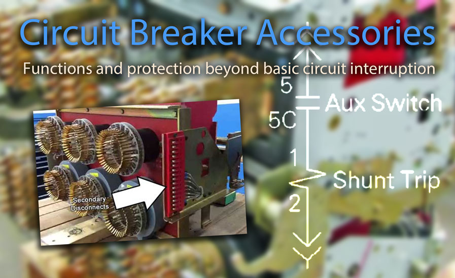
The purpose of accessories on a power circuit breaker is to provide additional functions and protection beyond basic circuit interruption. For example, a motor can automatically charge the closing spring of the breaker, reducing the time required for the breaker to close.
Other accessories can offer additional functions, such as undervoltage or overvoltage protection, or enable remote operation of the breaker. These accessories enhance the safety, reliability, and functionality of the power distribution system.
Circuit breaker accessories are matched to the system control voltage and may be available as factory-installed options or in field-installable kit form. Some typical control voltages include: 250VDC, 240VAC, 120VAC, 125VDC, 48VDC, 24VDC.
Auxiliary Switch
Auxiliary Switches provide remote indication of the breaker main contact position, changing state when the minimum isolating distance between the main contacts is reached. They typically feature Form C contacts, with options for both NO (Normally Open) and NC (Normally Closed) states, sharing a common neutral.
-
A Contact – Open or closed same as the breaker.
-
B Contact – Opposite to the breaker contacts.
Connected/Closed Switches
Connected/closed switches combine information from the “connected device” and “closed device,” indicating that the “circuit is closed.”
Bell Alarm / Overcurrent Trip Switch
The overcurrent trip switch provides remote indication that the circuit breaker has opened due to an electrical fault. Typically equipped with one set of Form C contacts, offering options for both NO (Normally Open) and NC (Normally Closed) states with a common neutral. The switch is activated, and the outputs change state whenever the breaker is tripped by an overcurrent, ground fault, or protective relay function via the Trip Unit.
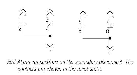
A trip caused by the manual OPEN button or by the Shunt Trip or Undervoltage Trip Device accessory does not activate the Bell Alarm. The accessory can be reset, returning the contacts to their normal configuration, by reclosing the breaker or by manually resetting the target on the breaker escutcheon.
Bell Alarm Lockout
The Bell Alarm with Lockout prevents closing of the breaker after a protection trip until the lockout is reset.
Electric Reset
The electric reset is used to reset the circuit breaker remotely after an electrical fault.
Ready-to-close Switch
The ready-to-close switch indicates that the following conditions are met and the circuit breaker can be closed:
- The circuit breaker is open
- The closing springs are charged
- The circuit breaker in not locked/interlocked in open position
- There is no standing closing order
- There is no standing opening order
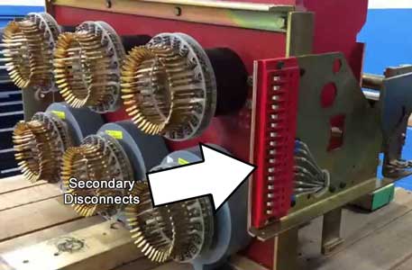
Secondary disconnects connect the circuit breaker to the control circuits. Photo: YouTube
Spring-Charging Motor
The spring-charging motor provides a means of electrically charging the closing springs automatically after the circuit breaker closes. When the springs are fully charged, a cutoff switch automatically de-energizes the motor. The closing springs will recharge automatically after the breaker closes unless an external switch contact is wired into the spring-charging circuit.
Spring-Charged Contact
The spring-charged contact indicates that the circuit breaker is charged. Usually a form C contact.
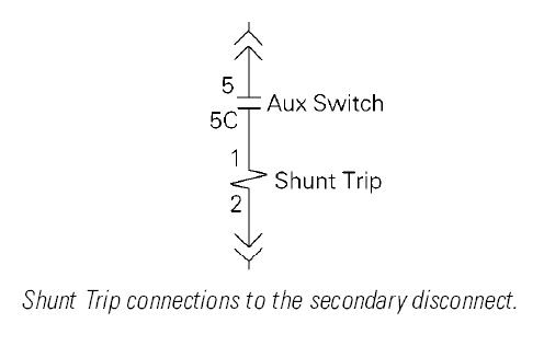
Shunt Trip / Shunt Close
The shunt trip coil opens the circuit breaker when energized. Shunt Close will close a circuit breaker when energized if the device is ready to close. Shunt trip and shunt close share the same coil; the action is determined by the location of the coil. The shunt close accessory features an anti-pump feature that prevents the breaker from repeatedly closing if the closing signal is maintained.
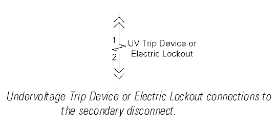
Undervoltage Trip
The undervoltage trip opens the circuit breaker when its supply voltage drops below the threshold voltage. Undervoltage trip coils require continuous power supply to keep the circuit breaker closed.
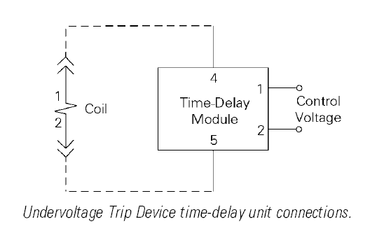
Time-Delay Module for Undervoltage Trip
The time-delay module for the undervoltage trip can be used to set an adjustable time delay before the undervoltage trip opens the circuit breaker, preventing nuisance tripping from a momentary voltage drop. The time-delay mechanism is connected in series with the undervoltage trip (MN) and is installed outside of the circuit breaker.
Electric Lockout
The electric lockout accessory uses a coil similar to an Undervoltage Trip Device to prevent the breaker from closing unless the coil is energized. Consequently, the breaker cannot be closed unless control voltage is applied; however, the loss of control voltage will not trip the breaker.
For instance, two breakers can be interlocked to ensure that they cannot both be closed simultaneously. The Electric Lockout coils on the two breakers to be interlocked can be wired in series with a normally closed Auxiliary Switch contact on the other breaker to provide the interlocking function. Mechanical bypass is utilized to permit cold startup when control power is not available.
Electrical Closing Push Button
The electrical closing push button closes the circuit breaker electrically via the shunt close. Requires installation of shunt close.
Operations Counter
The operations counter registers the total number of operating cycles for the circuit breaker.
Communications Module
The circuit breaker communications module provides communication between circuit breaker trip unit and the communication network. Dedicated switches can be used to read status of circuit breaker. Actuators can be used to control the circuit breaker.
Position Switch
The cell position switch indicates the circuit breaker position in the cradle/cell. This accessory is for drawout circuit breakers only and typically contains normally-open and normally-closed contacts. There can be one to three position switches for each type.
- Connected
- Disconnected
- Test
Open-Fuse Lockout
The Open-Fuse lockout is provided on integrally fused breakers or when the breaker is used in combination with a Fuse Rollout Element. When any fuse blows, the Open-Fuse Lockout trips the breaker to prevent single-phasing.
An indicator shows which fuse has blown. The breaker is mechanically trip-free and cannot be reclosed until the blown fuse is replaced, and the Open-Fuse Lockout is reset.
Hidden-Close Button
The Hidden Close Button is an unmarked replacement for the normal CLOSE button. Pressing the Hidden Close Button in the usual manner will not close the breaker; instead, a rod inserted with light pressure is used to engage the hidden-close button.