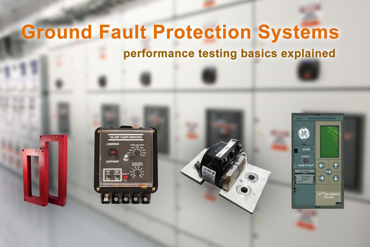
This guide provides a general overview of inspection and test procedures for simple residual and zero-sequence ground fault protection systems. Photo: TestGuy.
A ground fault is a type of electrical fault or short-circuit condition that results from any unintentional connection between an ungrounded conductor of an electrical circuit and the normally non–current-carrying conductors, metallic enclosures, metallic raceways, metallic equipment, or earth.
The resulting arc from a ground fault is so violent that it is capable of destroying electrical equipment faster than overcurrent protection can detect and clear the fault. This is possible because the system has sufficient voltage to maintain an arc between one phase and ground but not enough current to operate a main breaker or fuse.
For this reason, a separate form of protection is necessary to safeguard equipment from low-magnitude faults that are undetectable by overcurrent functions. Ground fault protection is required by the NEC and is usually installed only on circuits and services of 480/277 volts, 1,000 amps, and larger.
Performance testing of ground fault systems is required by National Electrical Code (NEC) sections 230.95(C) and 517.17(D). Ground fault protection can be provided for 3-wire and 4-wire equipment fed from a solidly grounded 4-wire supply, wye, or delta.
Ground-Fault Protection of Equipment (per Article 230.95 in NFPA 70-2017 (NEC)
“Ground-fault protection of equipment shall be provided for solidly grounded wye electric services of more than 150 volts to ground but not exceeding 1000 volts phase-to-phase for each service disconnect rated 1000 amperes or more.”
“The grounded conductor for the solidly grounded wye system shall be connected directly to ground through a grounding electrode system, as specified in 250.50, without inserting any resistor or impedance device.”
“The rating of the service disconnect shall be considered to be the rating of the largest fuse that can be installed or the highest continuous current trip setting for which the actual overcurrent device installed in a circuit breaker is rated or can be adjusted.”
Related: Ground Fault Protection: Basic Requirements and Exceptions
Ground Fault Relay Operating Principles
Ground fault protection systems operate on the principle of an imbalance between neutral and phase conductors. When a ground fault occurs in an electrical system, energized components make contact with grounded components, resulting in current flow through the grounding conductors.
With current that would normally flow back to the service entrance via the neutral conductor now diverted to the ground bus, less current is flowing back through the neutral conductor than what initially left through the phase conductor.
Current transformers are used to sense how much current is flowing through a conductor. There are two main current transformer arrangements used for this system:
1. Residual Sensor
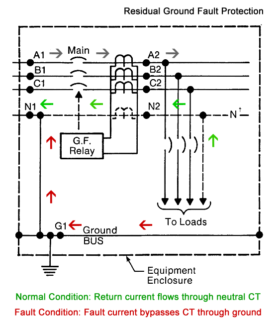
Example of a Residual Ground Fault Protection System. Photo: TestGuy.
When individual CTs are wired in opposite polarity in relation to neutral and phase conductors, the two signals will balance when an equal amount of current is flowing between them. If there is an imbalance in the signals, a secondary current will be produced that is used to activate the ground fault relay.
2. Zero-Sequence
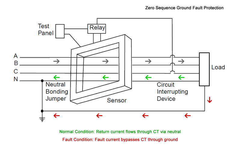
Example of a Zero-Sequence Ground Fault Protection System. Photo: TestGuy.
All phase conductors and neutral conductor (if applicable) pass through the window of a zero-sequence CT; the grounded conductor does not. When equal magnitudes of current flow between the phase and neutral currents, the signal is canceled out. If current flows through the ground conductor, it will not pass through the CT, resulting in an imbalance.
Performance Testing Basics
The ultimate reliability of the ground fault protection system depends on the strength of each element in the chain, such as solid-state sensor, monitor, control wiring, control power source, shunt trip, and circuit disconnecting means. If one element is incorrectly wired, inoperative, not calibrated, or damaged, the ground fault protection may not operate.
For this reason, complete periodic maintenance and electrical testing of the equipment by qualified personnel are necessary to check components and mechanisms that can fail, malfunction, and/or lose calibration.
Testing the Ground-Fault Protection System (per Article 230.95(C) in NFPA 70-2017 (NEC)
“The ground-fault protection system shall be performance tested when first installed on site. This testing shall be conducted by a qualified person(s) using a test process of primary current injection, in accordance with instructions that shall be provided with the equipment. A written record of this testing shall be made and shall be available to the authority having jurisdiction.”
Safety Considerations
Performance testing of ground fault protection systems should only be performed on de-energized electrical systems by qualified personnel. Particularly in tests requiring the use of a high-current test set, it is usually necessary to obtain the services of a qualified field testing organization. Because testing is conducted at the service entrance, a utility power outage is required on existing systems.
The test procedures described below consist of injecting full-scale primary current into the equipment phase and neutral conductors to duplicate the flow of ground fault current under various conditions. The testing equipment required includes a high-current supply capable of delivering up to 1000 amperes or more at 2.5 volts or similar.
By using the lower ground fault current pickup settings on relays and breakers or switches, the current required to trip can be kept to a minimum, such as 300 or 400 amperes or less. If inspection authorities require tests at full GFP setting, a current supply capable of delivering 1200 amperes or more may be needed.
Performance Testing Zero-Sequence Ground Fault Protection Systems
Zero-sequence ground fault protection is very simple to test. One of the most important checks is visual, making sure that only the correct number of phase and neutral conductors pass through the zero-sequence current sensor in the proper direction.
For performance testing, there are two tests to conduct:
1. No Trip Test
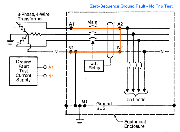
Zero-Sequence Ground Fault No Trip Test Example Test Procedure. Photo: TestGuy
Confirm that the neutral and phase conductors pass through the sensor and in the same direction by connecting the test current supply to points A1 and N1 with a jumper between A2 and N2. Main breaker should not trip when test current exceeds the predefined pickup and time delay setting.
2. Trip Test
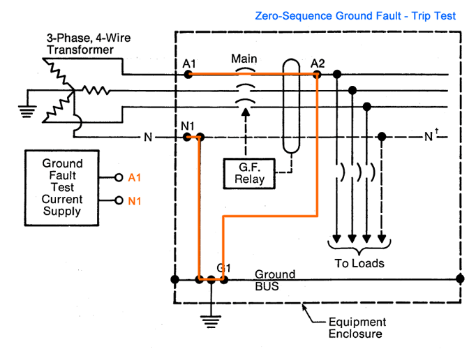
Zero-Sequence Ground Fault Trip Test Example Test Procedure. Photo: TestGuy
Confirm continuity of ground path from ground bus to neutral by connecting the test current supply to points A1 and N1 with a jumper between A2 and G1. Main breaker should trip when test current exceeds the predefined pickup and time delay setting.
Functional Test
For a quick verification of CT wiring and trip actuator, a single test lead can be passed through the zero-sequence sensor to produce a secondary current capable of activating the ground fault relay. If the required current cannot be achieved, the test lead can be wrapped around the sensor one or more times to multiply the secondary current produced by the sensor.
It’s important to note that this method does not verify that phase and neutral conductors go through the sensor in the same direction, nor does it verify the continuity of the ground path from ground bus to neutral.
Performance Testing Residual Ground Fault Protection Systems
NEC Article 250.23 requires that whenever a service is derived from a grounded neutral system, the grounded neutral conductor must be brought into the service entrance equipment and bonded to the equipment enclosure and ground bus, even if the grounded conductor is not needed for the load supplied by the service. This is required to provide a low-impedance ground fault current return path to the neutral to assure operation of the overcurrent device.
Before performance testing 3-phase 4-wire ground fault systems, the bonding jumper should be removed, and an insulation resistance test conducted between the neutral conductor and ground bus to ensure that no additional grounding connections have been made downstream from the main bonding jumper.
When additional grounding connections have been made downstream from the main bonding jumper, the sensitivity of the protection system is reduced. Once neutral and ground resistance is verified, reconnect the bonding jumper before proceeding with high current testing.
Four basic tests can be performed to verify operation of residual ground fault protection systems:
1. No Trip
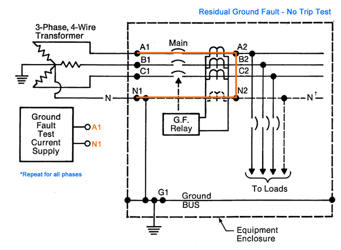
Residual Ground Fault Protection System - No Trip Example Test Procedure. Photo: TestGuy.
For a ground fault protection system to operate properly, correct neutral and phase CT polarity is essential. The no-trip test is wired to simulate normal load conditions, traveling through a phase sensor and back through the neutral sensor in the correct direction.
Confirm correct polarity of sensor connections by pushing test current at points A1 and N1 with a jumper from A2 to N2. Because the two current transformers cancel each other out, no trip is expected from the ground fault relay. Current should be raised and held above the pre-defined pickup setting for a duration longer than the predefined time delay.
2. Trip
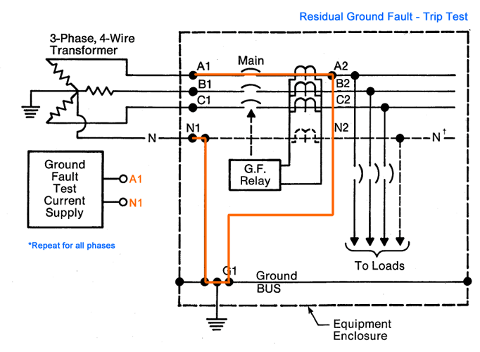
Residual Ground Fault Protection System - No Trip Example Test Procedure. Photo: TestGuy.
The trip test simulates a ground fault on the system by passing through a phase sensor and returning through the ground bus, effectively bypassing the neutral sensor through the bond jumper.
Confirm continuity of ground path from ground bus to neutral by connecting test current at points A1 and N1 with a jumper between points A2 and G1, the ground fault relay should trip once the applied current exceeds the predefined pickup setting for a duration within the manufacturers predefined time delay tolerance.
3. Half Trip

Residual Ground Fault Protection System - Half Trip Example Test Procedure. Photo: TestGuy.
When the required test current to trip the ground fault relay can’t be achieved, the half-trip test is an easy way to verify neutral sensor polarity. It’s called the half-trip test because it requires one-half the current required to perform a normal trip test.
The test uses the same connections as the no-trip test, except that the neutral lead is connected in the opposite expected polarity. When current is pushed through each CT, the half-trip has an additive effect, resulting in double the secondary current, instead of canceling out like in the no-trip test.
Perform this test by connecting test current supply to points A1 and N2 with a jumper between points A2 and N1, the ground fault relay should trip once the applied current exceeds half the predefined pickup setting for a duration within the manufacturers predefined time delay tolerance.
4. Neutral Sensor Trip
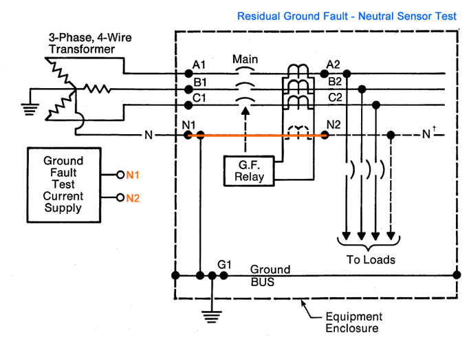
Residual Ground Fault Protection System - Neutral Sensor Example Test Procedure. Photo: TestGuy.
Ground fault protection systems can be activated by pushing current through only the neutral sensor, equivalent to the trip test without using a phase sensor. This is a quick, functional test that will demonstrate the operation of the neutral sensor, relay, and shunt trip. It does not prove that the relationship between the neutral and phase sensors is correct.
Verify neutral sensor function by connecting test current supply to points N1 and N2, the ground fault relay should trip once the applied current exceeds the predefined pickup setting for a duration within the manufacturers predefined time delay tolerance.
Other Considerations for Ground Fault Protection Systems
Because the ultimate reliability of the ground fault protection system depends on the strength of each element in the chain, other testing, in addition to injecting current through the current sensors to verify pickup and timing characteristics of the relay, should include:
- Test relay operation with reduced control voltage (one phase could be at 0 volts during a ground fault)
- Insulation resistance test control wiring to ensure adequate insulation and no shorts are present
- Check operation of special features like zone interlocks to verify time delay blocking capabilities
- Verify correct operation of all functions of the self-test panel.
- Electrical tests on current sensors such as ratio and insulation resistance.
References
- Ground Fault Protection Systems Performance Testing - GEI-48907
- What You Don’t Know About Ground Fault Protection Can Negatively Affect You and Your Equipment
- Ground Fault Protection - Cooper Bussmann
- Ground Fault Protection Testing: Why Test? - Vertiv
- ANSI/NETA Acceptance Testing Standards 2017
- ANSI/NETA Maintenance Testing Standards 2015