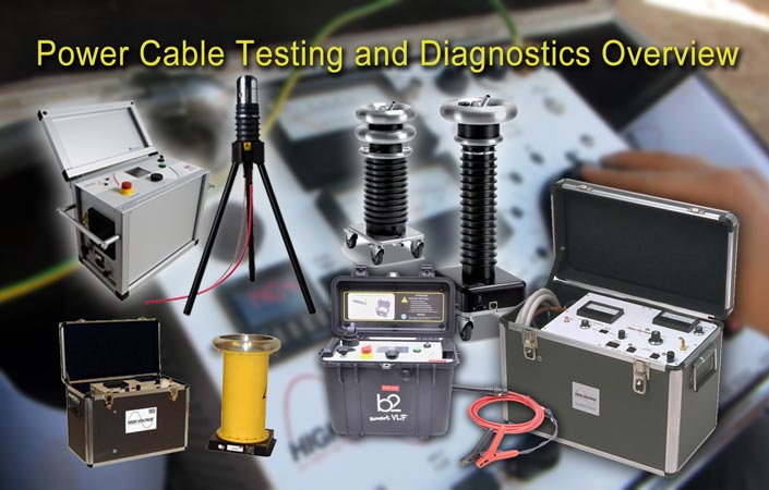
This article provides an overview of some commonly used maintenance and diagnostic techniques that are commercially available for performing tests in the field on medium- and high-voltage power cables. Photo: TestGuy.
Field testing of medium- and high-voltage cables may be performed for various reasons, such as acceptance after installation, charting the gradual deterioration of insulation over time, verification of splices and joints, and for special repairs. This assessment applies to both the cable itself and the associated accessories (splices and terminations) — referred to as the “cable system.”
In accordance with ICEA, IEC, IEEE and other consensus standards, testing can be performed by means of direct current, power frequency alternating current, or very low-frequency alternating current. These sources may be used to perform insulation-withstand tests, baseline diagnostic tests such as partial discharge analysis, and power factor or dissipation factor.
This article provides an overview of some commonly used maintenance and diagnostic techniques commercially available for performing tests in the field on medium- and high-voltage power cables.
Test Method Considerations
Due to the various cable testing methods available, a test method selection should only be made after evaluating each test method and conducting a thorough review of the installed cable system by a certified testing agency and the cable owner.
Safety Considerations
When testing cables, personnel safety is of the utmost importance. All cable and equipment tests should only be performed by qualified persons on isolated and de-energized systems, except where otherwise specifically required and authorized.
There are cases in which switches may be connected to a cable end and serve to isolate the cable from the rest of the system. Exercise extreme caution after de-energizing power cables, as they are capable of holding large capacitive charges. Use the correct personal protective equipment (PPE) and electrical safety tools to properly discharge cables before and after testing.
Types of Cable Tests
Field diagnostic tests can be performed on cable systems during various stages of their operating life. As defined by the IEEE 400 standard, cable tests are defined as:
-
Installation Test: Conducted after the cable is installed but before any accessories (joints/splices and terminations) are installed. These tests are intended to detect any manufacturing, transport, and installation damage that may have occurred to the cable.
-
Acceptance Test: Performed after the installation of all cable and accessories, but before energizing the cable with system voltage. Its purpose is to detect shipping and installation damage in both the cable and cable accessories. Also referred to as an “after-laying test.”
-
Maintenance Test: Performed throughout the service life of the cable system. Its purpose is to assess the condition and check the serviceability of the cable system so that suitable maintenance procedures can be initiated.
Methods of Cable Testing
Which test method to use depends greatly on the age and type of cable system installed. Many of the methods described in this article can be performed as an acceptance or maintenance test, depending on conditions such as the test voltage applied or duration of test.
Which test method to use depends greatly on the age and type of cable system installed.
The objective of any diagnostic test is to identify problems that may exist with a cable, in a non-destructive way, so that preventative measures can be taken to avoid potential failure of that cable when in service. Diagnostic assessments may apply to cable systems comprising the cable itself and the associated accessories such as splices and terminations.
Contents
- Dielectric Withstand Test
- Very low frequency (VLF)
- Damped alternating current (DAC) voltage
- Power factor / dissipation factor (tan delta)
- DC Insulation Resistance
- Partial discharge
- References
1. Dielectric Withstand Test
The dielectric withstand test is a basic electrical stress test conducted to ensure an insulation system will provide adequate service life. For the withstand test, the insulation under test must withstand a specified applied voltage that is higher than the service voltage across the insulation for a specified period without breakdown of the insulation.
The magnitude of the withstand voltage is usually far greater than that of the operating voltage, and the duration of application depends on service age and other factors. Dielectric withstand testing is a relatively easy test to perform. If no evidence of distress or insulation failure is observed by the end of the test, the specimen is considered to have passed.
If the applied voltage results in sudden breakdown of the insulation material, however, a strong leakage current will flow, and the insulation is determined to be unsuitable for service, as it might pose a shock hazard.
1a. Direct current (DC) dielectric withstand voltage
When conducting a DC hi-pot test, the voltage is gradually raised to the specified value with a steady rate of rise that produces a consistent leakage current until the final test voltage is reached. Anywhere from a minute to 90 seconds is generally considered sufficient for reaching the final test voltage.
The final test voltage is then held for 5-15 minutes, and if the leakage current is not high enough to trip the test set, the insulation is found to be acceptable. This type of test is usually performed after cable installation and repair.
DC hipot testing measures the insulation resistance of cables by applying high voltage and measuring leakage current, and the resistance is calculated using Ohm’s law. The test voltage values for DC hi-pot tests are based upon the final factory test voltage, which is determined by the type and thickness of insulation, the size of conductors, the construction of the cable, and applicable industry standards.
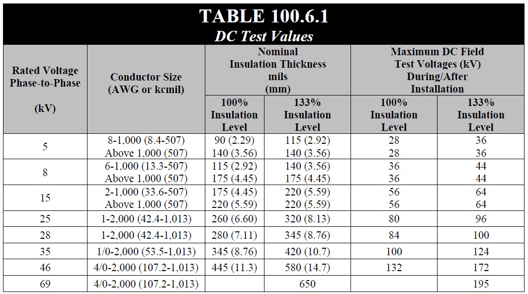
ANSI/NETA ATS-2021 Recommended DC Test Voltage for Power Cables. Photo: ANSI/NETA
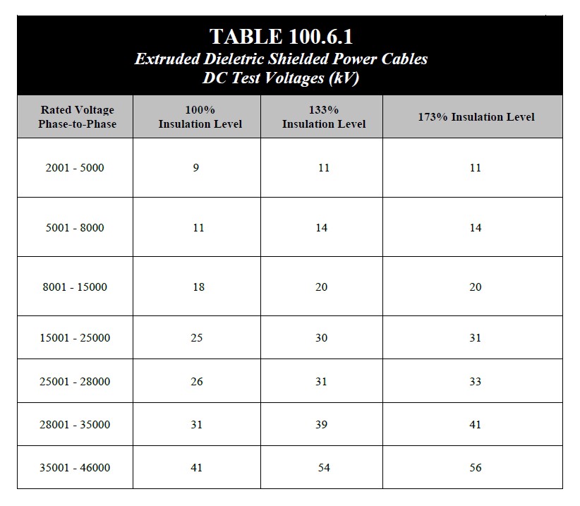
ANSI/NETA MTS-2023 Recommended DC Test Voltage for Power Cables. Photo: ANSI/NETA
It’s important to know that DC hi-pot testing does not provide a thorough analysis of cable condition but instead provides sufficient information as to whether the cable meets a specific high-voltage breakdown strength requirement. One advantage of a DC hipot test is that the leakage current trip points can be set to a much lower value than that of an AC voltage test.
In the past, DC dielectric withstand testing has been the most widely used test for acceptance and maintenance of cables. However, recent studies of cable failures indicate that the DC overpotential test may be causing more damage to some cable insulation, such as cross-link polyethylene (XLPE), than the benefit obtained from testing.
When maintenance testing existing in-service cables using a DC hi-pot, many factors should be considered to properly select the correct dielectric withstand test voltage. Generally, the highest values for maintenance should not exceed 60% of the final factory test voltage, and the minimum test value should be not less than the DC equivalent of the AC operating voltage.
Note: If the cable cannot be disconnected from all the connected equipment, the test voltage should be reduced to the voltage level of the lowest rated equipment connected.
1b. Power frequency (50/60 Hz) dielectric withstand voltage
Cables and accessories may also be withstand tested using power frequency voltage, although this is normally not done because it requires heavy, bulky, and expensive test equipment that may not be readily available in the field.
The AC test equipment used should have adequate volt-ampere (VA) capacity to supply the required cable charging current requirements of the cable under test. AC hi-pot tests can only be conducted as go-no-go tests and therefore may cause extensive damage should the cable under test fail.
If AC hi-pot acceptance and maintenance tests are to be conducted on cables, then it should be recognized that this test is not very practical. The most common field tests performed on cables are DC hi-pot or VLF tests instead of AC hi-pot tests.
While it may not be very practical in the field, the AC hi-pot test has the distinct advantage of stressing cable insulation comparable to normal operating voltage. This test replicates the factory test performed on the new cable.
AC hipot tests include capacitive current and resistive current in parallel; the source frequency plays the largest role in the amount of power required to charge the capacitance of a test specimen. When performing the AC hi-pot test, consideration should be given to the adequacy of the test equipment for successfully charging the test specimen.
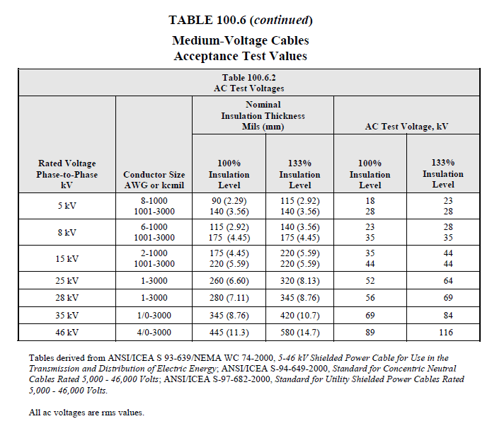
ANSI/NETA ATS-2017 Recommended AC Test Voltage for Power Cables. Photo: ANSI/NETA
2. Very low frequency (VLF) dielectric withstand voltage
VLF testing can be classified as a withstand or diagnostic test, meaning it may be performed as a proof test for acceptance or as a maintenance test for assessing the condition of the cable. Unlike with DC voltage testing, very low frequency is not destructive to good insulation and does not lead to premature failures.
VLF testing is performed with an AC hi-pot at a frequency ranging from 0.01 to 1 Hz. The most widely accepted test frequency is 0.1 Hz; however, frequencies in the range of 0.0001–1 Hz may be useful for diagnosing cable systems that exceed the limitations of the test system at 0.1 Hz.
The procedure for VLF testing is nearly identical to that of DC hi-pot testing and is also conducted as a go-no-go test. If the cable can withstand the applied voltage for the duration of the test, it is considered a pass.
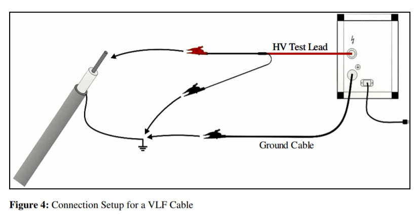
VLF Cable Test Connection Setup Diagram. Photo: High Voltage, Inc.
Proper test voltage and time duration are critical for the success of the VLF test. If the applied test voltage used is too low and/or too short in duration, the risk of failure in service may increase following the test.
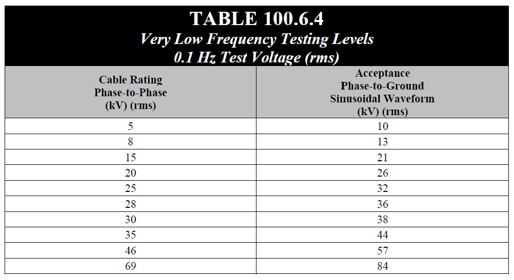
ANSI/NETA ATS-2021 Recommended VLF Test Voltage. Photo: ANSI/NETA
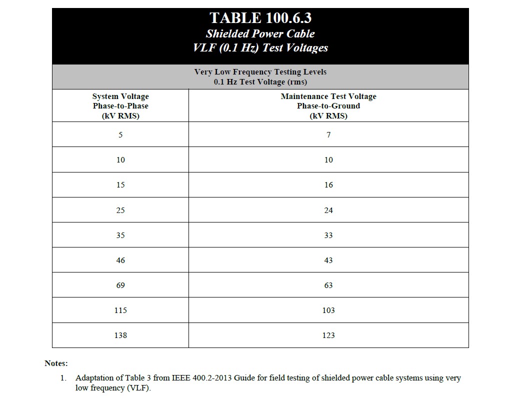
ANSI/NETA MTS-2023 Recommended VLF Test Voltage. Photo: ANSI/NETA
VLF testing is not only used for testing solid dielectric cable, any application requiring AC testing of high capacitance loads can be tested using very low frequency. The major application is for testing solid dielectric cable (per IEEE 400.2), followed by testing large rotating machinery (per IEEE 433), and occasionally for testing large insulators, arrestors, etc.
3. Damped alternating current (DAC) voltage
DAC voltage testing is one of the alternative methods of AC voltage testing and is applicable for a broad range of medium-voltage, high-voltage, and extra-high-voltage cables. Damped alternating current voltages are generated by charging the test object to a predetermined voltage level and then discharging its capacitance through a suitable inductance.
During the discharging stage, a DAC at a frequency dependent on the test-object capacitance and the inductance is present. The capacitance of the test object is subjected to a continuously increasing voltage at a rate dependent on the test-object capacitance and the current rating of the power supply.
Most DAC applications are based on the combination of voltage withstand and advanced diagnostic measurements, such as partial discharge and dissipation factor. DAC testing is an advanced maintenance tool, offering more than a simple “go or no-go” decision.
4. Power factor / dissipation factor (tan delta)
Tan Delta, also called Loss Angle or Dissipation Factor (DF) testing, is a diagnostic method of testing cables to determine the quality of the insulation. If the insulation of a cable is free from defects like trees, moisture, and air pockets, etc., the cable approaches the properties of a perfect capacitor.
In a perfect capacitor, the voltage and current are phase-shifted 90 degrees, and the current through the insulation is capacitive. If there are impurities in the insulation, the resistance of the insulation decreases, resulting in an increase in resistive current through the insulation.
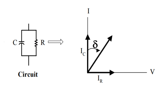
Tan Delta / Dissipation Factor Angle. Photo: High Voltage, Inc.
The cable becomes a less perfect capacitor, and the phase shift will be less than 90 degrees. The extent to which the phase shift is less than 90 degrees is called the “loss angle,” which indicates the level of insulation quality/reliability.
Cables with poor insulation have higher DF values than normal and will exhibit higher changes in the tangent delta values with changes in applied voltage levels. Good cables have low individual TD values and low changes in tangent delta values with higher applied voltage levels.
In practice, a very low frequency AC Hi-pot is most often used as the voltage source to energize cable for tangent delta tests. Very low frequency is the preferred method over 60Hz for two reasons:
-
The increased load capability in field applications in which 60 hertz is too bulky and expensive, making it nearly impossible to test a cable of considerable length. At a typical VLF frequency of 0.1Hz, it takes 600 times less power to test the same cable compared to 60 Hz.
-
The magnitude of tan delta numbers increase as frequency decreases, resulting in easier measurements.
When performing tan delta, the cable to be tested must be de-energized and each end isolated. Test voltage is applied to the cable while the tan delta test set takes measurements.
The applied test voltage is raised in steps, with measurements first taken up to 1Uo, or normal line to ground operating voltage. If the tan delta numbers indicate good cable insulation, the test voltage is raised up to 1.5 – 2Uo.
The test itself can take less than twenty minutes, depending upon the settings of the instrument and the number of different test voltage levels used. It is only necessary to capture a few cycles of the voltage and current waveform to make the analysis.
5. DC Insulation Resistance
The insulation resistance of cable is measured using a Megohmmeter. This is a simple, nondestructive method of determining the condition of the cable insulation to check for contamination due to moisture, dirt, or carbonization.
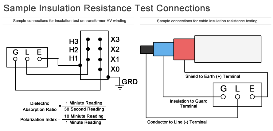
Sample insulation resistance megohmeter test connections for cable and transformer using Guard terminal. Photo: TestGuy.
Insulation resistance measurements should be conducted at regular intervals, and test records kept for comparison purposes. A continued downward trend is an indication of insulation deterioration even though the resistance values measured are above the minimum acceptable limit.
The readings must be corrected to a base temperature (such as 20°C) for a valid comparison. Keep in mind that insulation resistance measurements do not give the measure of the total dielectric strength of cable insulation or weak spots in the cable.
When overpotential testing a cable, it’s common practice to conduct the insulation resistance measurement first and then proceed with the DC overpotential test if acceptable readings are achieved. After the DC overpotential test is completed, the insulation resistance test is done again to assure that the cable has not been damaged by the hi-pot.
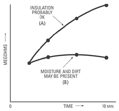
Typical curves showing dielectric absorption effect in a “time-resistance” test, made on capacitive equipment such as a large motor winding. Photo Credit: Megger US.
PI and DAR
Polarization Index is another insulation resistance test method that evaluates insulation quality based on the change in Megohm value over time. After voltage is applied, the IR value is read at two different times: usually either 30 and 60 seconds (DAR), or 60 seconds and 10 min (PI).
“Good” insulation will show a gradually increasing IR value over time. When the second reading is divided by the first reading and the resulting ratio is called the dielectric absorption ratio (DAR) or polarization index (PI).
6. Partial discharge
Partial Discharge is a localized electrical discharge that can occur at voids, gaps, and similar defects in medium and high voltage cable systems. If not properly addressed, partial discharge will erode the cable insulation, usually forming a tree-shaped pattern of deterioration (electrical tree) and eventually result in complete breakdown and failure of the cable or accessory.
Testing involves applying a voltage conducive to partial discharge and then directly or indirectly measuring the discharge current pulses using calibrated PD sensors. Characteristics of partial discharge depend on the type, size, and location of the defects, insulation type, voltage, and cable temperature.
The PD test is known to detect small imperfections in the insulation such as voids or skips in the insulation shield layer; however, PDs must be present to detect any PD. Measurements can be made on newly installed and service-aged cables to detect any damage created during the installation of new cable or in-service degradation of cable insulation due to PDs.
6a. Online PD (50/60 Hz)
Performed without disrupting service, Online Partial Discharge testing is a non-destructive, non-invasive predictive maintenance tool that gauges the condition of aging cable systems based on measuring PDs at the cable-operating voltage.
6b. Off-Line PD
Offline Partial Discharge Testing offers a significant advantage over other technologies because of its ability to measure the cable system’s response to a specific stress level and predict its future performance without causing a fault. Offline testing is also known for its ability to pinpoint the exact defect location on field-aged equipment, enabling the asset manager to accurately plan for maintenance and repair.
The challenge with offline testing is that the equipment must be taken out of service. Measurements are done at a higher voltage than cable operating voltage to reinitiate PD activity in the de-energized cable, which increases the risk of failures during the test.
The test duration should be long enough to allow the availability of electrons to initiate PDs, but once PDs are detected, the voltage should be applied long enough only to collect sufficient PD data.
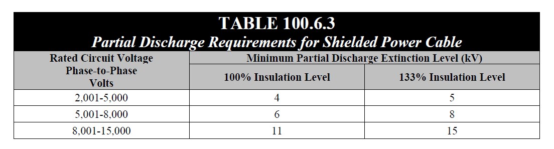
ANSI/NETA ATS-2021 Partial Discharge Requirements. Photo: ANSI/NETA
References
- ANSI/NETA Acceptance Testing Standards 2017
- ANSI/NETA Maintenance Testing Standards 2015
- Electrical Power Equipment Maintenance and Testing, Second Edition
- The Dielectric Voltage Withstand Test: Benefits and Limitations (Archived)
- VERY LOW FREQUENCY AC HIPOTS A REVIEW OF VLF TESTING & ANSWERS
- VLF AC WITHSTAND TESTING of CABLE Voltage Levels & Time Durations of Test
- VLF Testing of Shielded Power Cables
- Tan Delta Cable Testing Questions and Answers
- Understanding Insulation Resistance Testing
- ONLINE OFFLINE PARTIAL DISCHARGE TESTING FOR CABLE ASSESSMENT
- What Is Partial Discharge Testing?