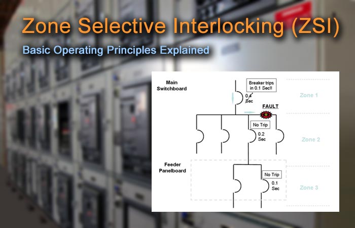
This guide provides a basic overview of zone selective interlocking principles and test procedures. Photo: TestGuy
Zone selective interlocking (ZSI) is a communication scheme employed with circuit breakers and protective relays to enhance the level of protection in a power distribution system. Also referred to as zone restraint, the primary objective of this scheme is to mitigate the stress on electrical distribution equipment during short-circuit or ground-fault conditions.
In a coordinated system, longer delays and higher pickups are chosen for upstream devices to enable downstream devices to trip first. This leads to extended tripping times as circuit breakers wait for the designated delay time before tripping, potentially exposing the system to significant fault stress.
Downstream branch devices should operate swiftly, without intentional delays, while main devices should introduce a delay in their operation, allowing downstream devices ample time to clear the fault. ZSI works to limit fault stress on equipment by reducing the time it takes to clear the fault while maintaining system coordination between overcurrent and ground-fault protective devices.
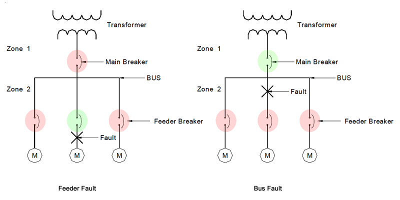
Example of protective device coordination during a feeder fault and bus fault. Photo: EATON.
In a coordinated system, only the device nearest to the fault will trip unless the coordinated protection levels are exceeded. Zone interlocking works in parallel with the coordinated protection of a power distribution system, ensuring that the nominal protection levels are not compromised.
ZSI System Operation
Zone interlocks communicate fault conditions across zones. A zone is a section of the power distribution system that is connected at a common point and classified by its location downstream of the main circuit protective device.
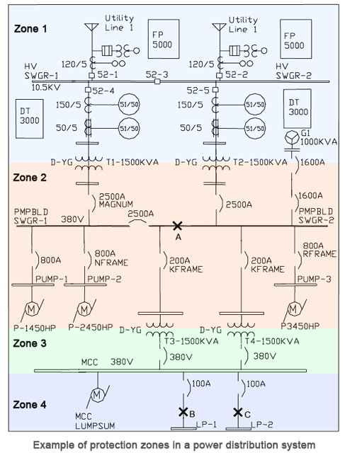
Example of protection zones in an electrical power distribution system. Photo: EATON.
If a major fault occurs in the system, the device closest to the fault will be given the opportunity to clear the condition without disrupting service to other areas of the facility. The preset time delay on the overcurrent device is deactivated, and the device will clear the fault with no intentional delay.
When a downstream fault exceeds the ground fault and/or short-time pickup on both the Main and Feeder, each device will detect the fault. The Feeder sends a restraint signal upstream to the Main, activating the preset time delay, giving the feeder a chance to clear the fault.
If the feeder does not receive a restraint signal, it opens to clear the fault with no intentional delay. Since the Main’s preset time delay is activated, proper selectivity and coordination are maintained while still providing backup protection for the Feeder and other downstream devices.
Because zone selective interlocking works in parallel with the coordinated protection of a power distribution system, the use of ZSI will not cause circuit breakers that are not coordinated (due to improper settings) to coordinate.
Self-Interlocking
If preferred, the restraint signal can be defeated by feeding the output signal to the input. This can be accomplished simply by placing a jumper between the output and input signals on the device.
When a system disturbance occurs, the signal output will be fed into the input, thus defeating an instantaneous response. This may be applicable to breakers that serve loads which should not be interrupted unless the coordinated protection limits are exceeded.
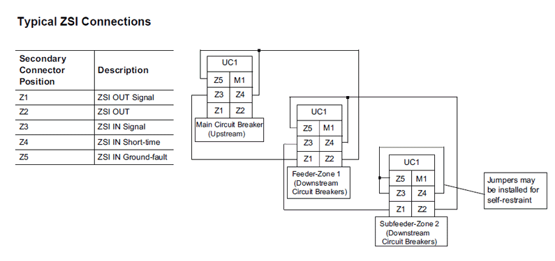
Example zone-selective interlocking wiring diagram. Consult manufacturers literature to locate ZSI terminals for your specific protective device. Photo: Square D.
Performance Testing
The ZI signal will need to be defeated when performing tests on circuit breakers and relays to properly verify the time delay function of a protective device. If zone interlocking is not defeated during testing, the protective device will trip instantaneously regardless of the time delay setting being used.
Verify zone interlock operation by conducting a short time and/or ground fault time delay test. Perform two separate tests, one with and one without a self-interlocking jumper, to observe both instantaneous and time delay trips. The recorded time delay should fall within the coordinated time-current curve.
Related
- Ground Fault Protection Systems: Performance Testing Basics
- Characteristics of Circuit Breaker Trip Curves and Coordination
Effects of Transformer Inrush Current on ZSI
Applying zone interlocking on the primary side of a transformer may cause unwanted tripping due to high inrush currents that may exceed 12 times the full load ampere (FLA) rating of the transformer with the secondary open.
To prevent the breaker on the primary side from tripping in a nuisance condition, a self-interlocking jumper should be installed during the energizing of the transformer, which can last from 10 cycles to several minutes.
Zone Interlocking Overview
-
When a device equipped with ZSI senses a short circuit or ground fault, it sends a restraint signal to the ZSI device just upstream from it. This action activates the preset time delay on the upstream device.
-
If a device equipped with ZSI senses a short circuit or ground fault and does not receive a restraint signal, its preset time delay will not be activated, and it will trip with no intentional delay.
-
Without ZSI, a coordinated system results in the circuit breaker closest to the fault clearing the fault, usually with an intentional delay. With ZSI, the device closest to the fault will ignore its preset short-time and/or ground-fault delays and clear the fault with no intentional delay.