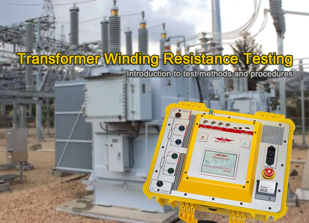
This guide provides an introduction to transformer winding resistance test methods and procedures. Photo: TestGuy
Winding resistance measurements are crucial diagnostic tools for assessing potential damage to transformers caused by factors such as poor design, assembly, handling, unfavorable environments, overloading, or inadequate maintenance.
The primary purpose of this test is to identify significant differences between windings and detect any open connections. Measuring the resistance of transformer windings ensures that each circuit is wired correctly and that all connections are securely tightened.
The winding resistance in transformers can vary due to shorted turns, loose connections, or deteriorating contacts in tap changers. Regardless of the configuration, the resistance measurements are normally made phase-to-phase and the readings are compared with each other to determine if they are acceptable.
Transformer winding resistance measurements are obtained by passing a known DC current through the winding under test and measuring the voltage drop across each terminal (Ohm’s Law). Modern test equipment for this purposes utilizes a Kelvin bridge to achieve results; you might think of a winding resistance test set as a very large low-resistance ohmmeter (DLRO).
Related: Test Equipment 101: The Basics of Electrical Testing
Guide Contents
- Connecting the Test Set
- Connecting to the Transformer
- Obtaining Winding Resistance Measurements
- Tap Changer Winding Resistance
- Test Results
- Temperature Correction Formula
- Transformer Demagnetization
Use Caution When Testing!
Before conducting a transformer winding resistance test, it is important to observe all safety warnings and take proper precautions. Ensure that all equipment to be tested is properly grounded, and treat all high-voltage power equipment as energized until proven otherwise by using the proper lockout/tagout procedures.
During the test, it is important not to remove current or voltage leads while current is still flowing through the transformer. This action could cause an extremely high voltage to develop across the point where the current is broken, posing a risk of lethal voltage.
Related: Electrical Shock and Arc Flash PPE Overview
Connecting the Test Set
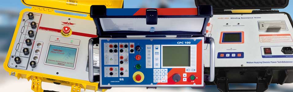
Transformer Winding Resistance Test Equipment. Photo: Testguy
Winding resistance test equipment is available in a variety of styles based on specific applications. A test set used for a power transformer would be much different than one designed for small instrument transformers. Regardless of the type, winding resistance testers are always equipped with a current output, voltage measurement, and resistance meter.
Both the primary and secondary terminals of the transformer should be isolated from external connections, and measurements made on each phase of all windings. Test equipment connections should be made in the following order:
-
Ground – Ensure that the transformer is first grounded directly to the local station ground, and then attach the test set ground.
-
Accessories – Connect any desired accessories, such as remote controls, warning beacon, PC, etc.
-
Test Leads – With the test leads disconnected from the device under test, connect the current and voltage leads to the test set and verify tightness of all connections.
-
Connect to the transformer – Each transformer configuration requires different test connections; some examples are provided in the next section. Extra care should be taken to prevent leads from falling off while testing or connecting leads on top of or too close to one another. Voltage leads should always be placed inside (between) current leads and the transformer.
-
Input power – Plug in the test set. Before making this connection, ensure that the power source ground has a low-impedance path to the local station earth ground.
Connecting to the Transformer Under Test
For single-phase and simple Delta-Wye configurations, the following connections can be used. Keep in mind that each transformer configuration is different, and your specific setup may not apply to what is shown below. Consult the user manual that came with your test kit for more information.
Single Phase Transformer Example
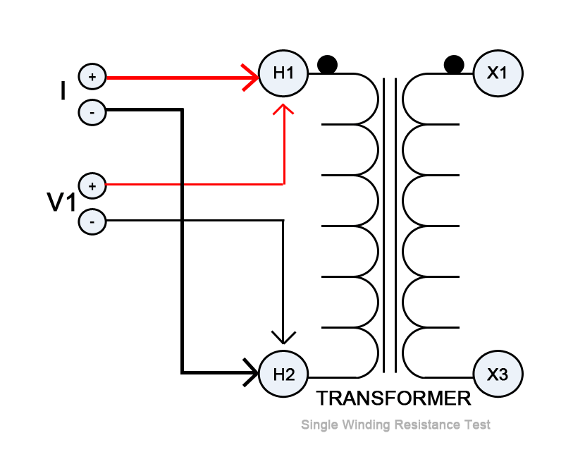
Transformer Winding Resistance Test Connections - Single Winding. Photo: TestGuy
3-phase Delta Winding Example
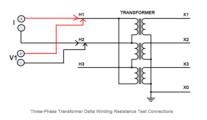
Transformer Winding Resistance Test Connections - 3-phase Delta Winding. Photo: TestGuy
| Test No. | I+ | I- | V1+ | V1- | V2+ | V2- |
|---|---|---|---|---|---|---|
| A-phase | H1 | H2 | H1 | H2 | -- | -- |
| B-phase | H2 | H3 | H2 | H3 | -- | -- |
| C-phase | H3 | H1 | H3 | H1 | -- | -- |
3-phase Wye Secondary Winding Example
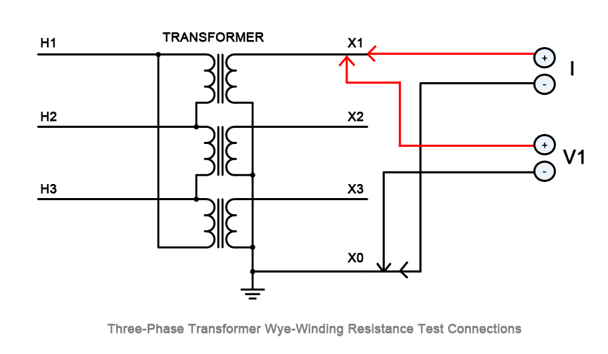
Transformer Winding Resistance Test Connections - 3-phase Wye Winding. Photo: TestGuy
| Test No. | I+ | I- | V1+ | V1- | V2+ | V2- |
|---|---|---|---|---|---|---|
| A-phase | X1 | X0 | X1 | X0 | -- | -- |
| B-phase | X2 | X0 | X2 | X0 | -- | -- |
| C-phase | X3 | X0 | X3 | X0 | -- | -- |
Dual Winding Test Example (Single Phase)
To save time when testing two-winding transformers, both primary and secondary windings can be tested at the same time using the connections shown below:
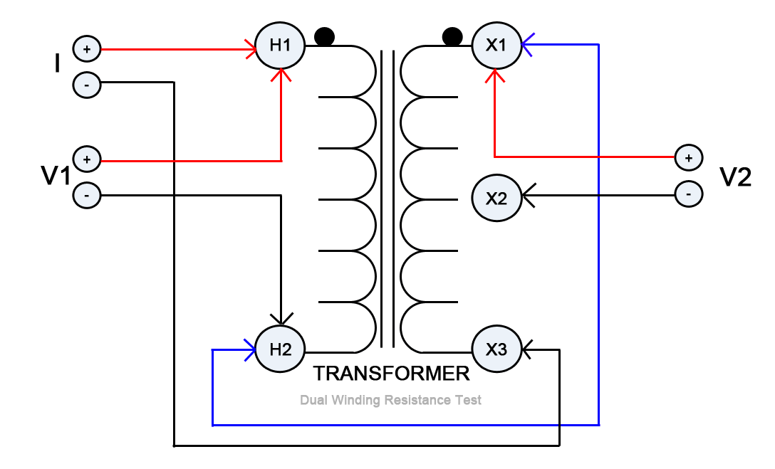
Transformer Winding Resistance Test Connections - Dual Winding. Photo: TestGuy
| Test No. | I+ | Jumper | I- | V1+ | V1- | V2+ | V2- |
|---|---|---|---|---|---|---|---|
| 1 | H1 | H2-X1 | X3 | H1 | H2 | X1 | X2 |
Dual Winding Test Example (Three-Phase)
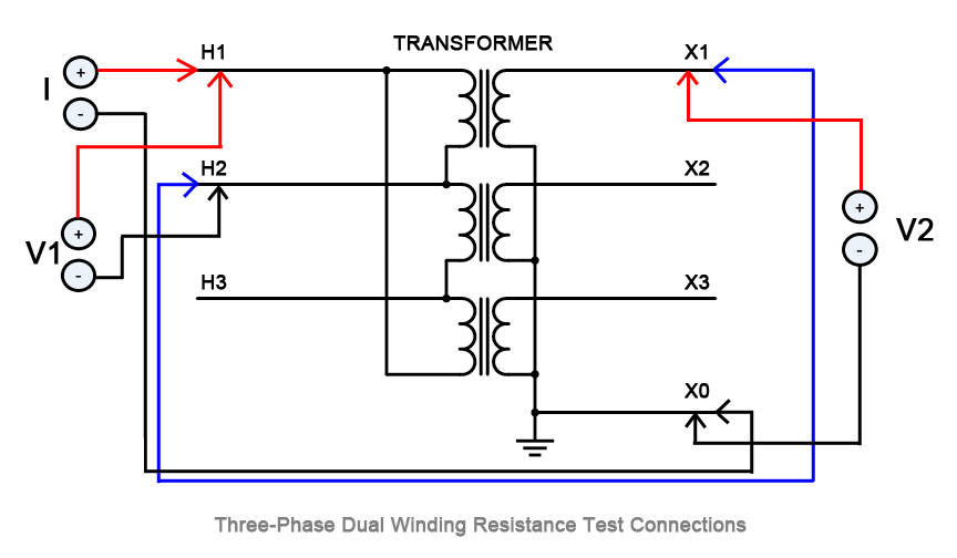
3-Phase Transformer Dual Winding Resistance Test Connections. Photo: TestGuy
| Test No. | I+ | Jumper | I- | V1+ | V1- | V2+ | V2- |
|---|---|---|---|---|---|---|---|
| A-Phase | H1 | H2-X1 | X0 | H1 | H2 | X1 | X0 |
| B-Phase | H2 | H3-X2 | X0 | H2 | H3 | X2 | X0 |
| C-Phase | H3 | H1-X3 | X0 | H3 | H1 | X3 | X0 |
To reduce core saturation time, the jumper used to connect both windings should be connected to opposite polarities of the transformer. If the positive lead for the current is connected to the positive terminal of the primary winding, drive the test current from the primary winding H2 jumped to the positive terminal of the secondary winding X1.
Note: If the resistance between the two windings is greater than a factor of 10, it may be desirable to obtain more accurate readings by testing each winding separately.
Current Transformer Example
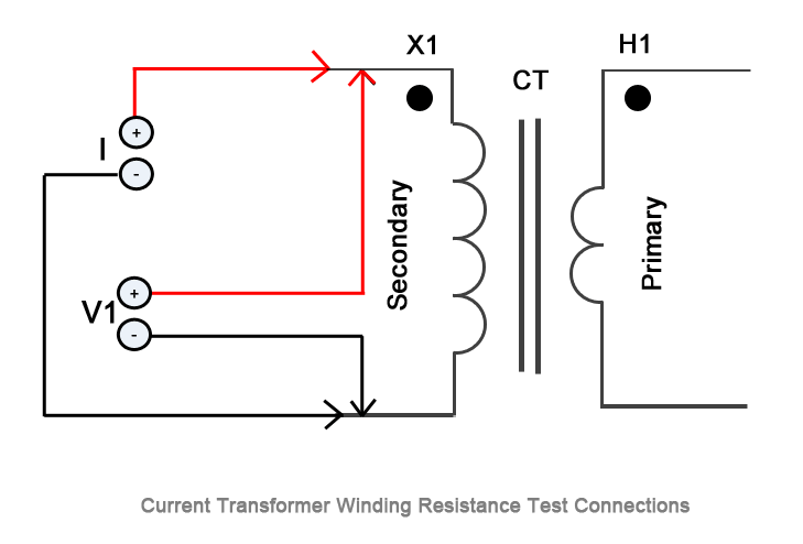
Current Transformer Winding Resistance Test Connections. Photo: TestGuy
Obtaining Winding Resistance Measurements
When measuring winding resistance, the reading should be observed and recorded once the resistance value has stabilized. Resistance values will “drift” at first due to the inductance of the transformer, which is more prevalent in large, delta connected windings.
For small transformers, the drift lasts for only a few seconds; for single-phase high-voltage transformers, the drift may last for less than a minute; for large transformers, the required drift time could last a couple of minutes or more. Any change in current will cause the resistance value to change.
Tap Changer Winding Resistance
Many power and distribution transformers are equipped with tap changers to increase or decrease the turns ratio depending on the supply voltage. Because changing the ratio involves a mechanical movement from one position to another, each tap should be checked during a winding resistance test.
During routine maintenance, it may not always be feasible to test each tap due to time constraints or other factors. In such cases, it’s acceptable to measure the resistance of each winding at only the designated tap position.
For “Off-load” taps, the transformer must be discharged between tap changes. “On-load” tap changers and voltage regulators may be operated with the test set left on while changing from tap to tap. This not only saves time but can also verify the make-before-break function of the tap changer.
Related: Transformer Tap Changers: Basic Principles and Testing Explained
Test Results
Interpretation of winding resistance results is usually based on a comparison of each resistance value with each adjacent winding at the same tap. If all readings are within one percent of each other, the specimen is considered to have passed the test.
Comparisons may also be made with original test data measured at the factory by using temperature-corrected values, keeping in mind that resistance tests in the field are not meant to duplicate the manufacturer’s test record. The manufacturer’s test was most likely performed in a controlled environment at the time of manufacture.
Sample Test Data
Depending on the size of the transformer winding under test, resistance readings will be expressed as ohms, milliohms, or microhms. The table below demonstrates how test data for a simple 13,200-208/120V three-phase transformer with three primary de-energized tap changer positions can be recorded.
| WINDINGS | TAP POSITION | RESISTANCE (MILLIOHMS) |
|---|---|---|
| H1-H2 | 1 | 750.3 |
| H2-H3 | 1 | 749.8 |
| H3-H1 | 1 | 748.5 |
| H1-H2 | 2 | 731.8 |
| H2-H3 | 2 | 731.4 |
| H3-H1 | 2 | 729.4 |
| H1-H2 | 3 | 714.6 |
| H2-H3 | 3 | 714.3 |
| H3-H1 | 3 | 712.3 |
| X1-X0 | N/A | 0.3550 |
| X2-X0 | N/A | 0.3688 |
| X3-X0 | N/A | 0.3900 |
Temperature Correction
Because resistance is dependent on temperature, corrected values must be used whenever comparing results for trend data. It’s most important to estimate the winding temperature at the time of measurement.
If the transformer has a winding temperature gauge, use these readings; otherwise, the winding temperature is assumed to be the same as the oil temperature. If the transformer is measured without oil, the winding temperature is normally assumed to be the same temperature as the surrounding air.
Related: 3 Routine Inspections and Checks for Liquid Filled Transformers
The measured resistance should be corrected to a common temperature such as 75°C or 85°C using the following formula:
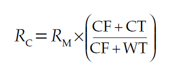
where:
- RC is the corrected resistance
- RM is the measured resistance
- CF is the correction factor for copper (234.5) or aluminum (225) windings
- CT is the corrected temperature (75°C or 85°C)
- WT is the winding temperature (°C) at time of test
Transformer Demagnetization
Once all testing is complete, perform a demagnetization operation on the transformer. This step is critical for smooth operation when placing the transformer into service.
Demagnetizing a transformer removes the residual magnetic flux caused by passing a polarized direct current through the windings during resistance testing. Photo: Wikimedia.
If a demagnetization operation is not performed, excess residual flux in the transformer core may cause large inrush currents on the primary side that could trip the protective relays. Demagnetization of the transformer is achieved by passing multiple cycles of reduced current through a winding in both the positive and negative direction (alternating DC).
Demagnetization only needs to be performed on a single winding once all of the resistance tests are complete. When using modern test sets with a demagnetization function, it’s recommended that both current and voltage leads be attached to a high side winding for the demagnetization process.
For current transformers, run a saturation test to demagnetize the CT at the completion of all winding resistance tests.