Mimic bus symbols accurately reflect the distribution system arrangement that they are producing. Photo: Sage Controls, Inc.
The primary function of the electric power distribution system in a building or facility is to receive power at one or more supply points and deliver it to lighting, elevators, chillers, motors, and all other electrical loads.
The best distribution system is one that will, cost-effectively and safely, supply adequate electric service to both present and future probable loads. The selection of a system arrangement has a profound impact on the reliability and maintainability of the electrical system.
Four basic circuit arrangements are used for the distribution of electric power: radial, primary selective, secondary selective, and secondary network circuit arrangements.
Several commonly used electrical distribution systems are discussed below. It is usually necessary to combine two or more of these arrangements for increased system reliability.
Related: Electrical Substation Bus Schemes Explained
Contents
- Radial system
- Expanded Radial system
- Radial system with Primary Selectivity
- Primary and Secondary Simple Radial system
- Primary Loop system
- Secondary Selective system
- Primary Selective system
- Sparing Transformer system
- Secondary Spot Network
- Composite Systems
1. Radial system
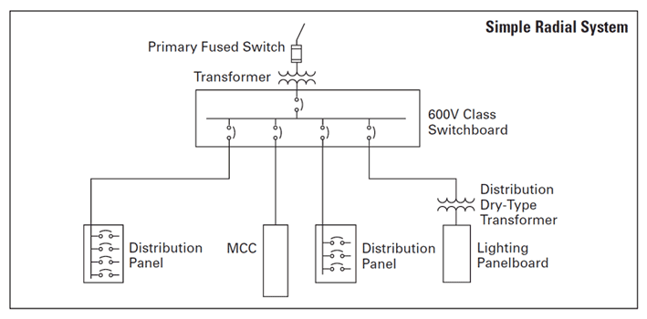
The radial system is the simplest electrical distribution arrangement, and the least expensive in terms of equipment initial cost. It’s also the least reliable arrangement since it only uses a single utility source.
With the simple radial system, the loss of the utility source, transformer, or the service or distribution equipment will result in a loss of service. Photo: EATON.
The conventional simple radial system receives power at the utility supply voltage at a single substation and steps the voltage down to the utilization level. The loss of the utility source, transformer, or the service or distribution equipment will result in a loss of service.
Furthermore, the loads must be shut down to perform maintenance on the system. This arrangement is most commonly used where the need for low initial cost, simplicity, and space economy outweigh the need for enhanced reliability.
Typical equipment for this system arrangement is a single-unit substation consisting of a fused primary switch, a transformer of sufficient size to supply the loads, and a low-voltage switchboard.
2. Expanded Radial System
One of the main advantages of the simple radial system is that it can easily be expanded by the inclusion of additional transformers. Reliability increases with a larger number of substations since the loss of one transformer will not result in a loss of service for all loads.
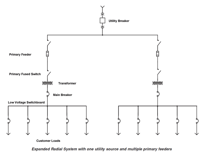
Photo: The simple radial system can easily be expanded by the inclusion of additional transformers. Square D.
To minimize voltage drop, the additional transformers can be located close to the center of each group of loads. If the loss of a transformer or feeder can’t result in the loss of service to a part of the facility, a more reliable system arrangement is required.
3. Radial system with Primary Selectivity
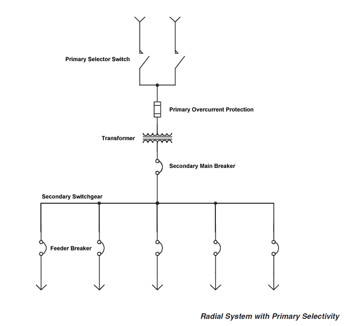
When two utility sources are available, radial systems with primary selectivity provide almost the same economic advantages as the simple radial system with greater reliability, as the failure of one utility source will not result in a total loss of service.
Primary selectivity brings greater reliability to the radial system since the failure of one utility source will not result in a total loss of service. Photo: Square D.
A brief outage will occur between the loss of the primary utility source and switching to the alternate source unless the utility sources are paralleled. The loss of the transformer or distribution equipment would still result in a loss of service.
An automatic transfer scheme may be used between the two primary sources to automatically switch from a failed utility source to an available source. Maintenance on the primary system requires all loads to be shut down.
Related: Transfer Switch Testing and Maintenance Guide
4. Primary and Secondary Simple Radial system
An improved form of the conventional simple radial system distributes power at a primary voltage. The voltage is stepped down to the utilization level in several load areas, typically through secondary unit substation transformers.
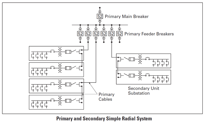
In the Primary and Secondary Simple Radial system, a fault on a primary feeder circuit or in one transformer will cause an outage to only those secondary loads served by that feeder or transformer. Photo: EATON.
Each secondary unit substation is an assembled unit consisting of a transformer, an integrally connected primary fused switch, and low-voltage switchgear or switchboard. Circuits are fed to each load from circuit breakers or fused switches.
A fault on a primary feeder circuit or in one transformer will cause an outage only to those secondary loads served by that feeder or transformer. In the case of a primary main bus fault or a utility service outage, service is interrupted to all loads until the trouble is eliminated.
Because power is distributed to the load areas at a primary voltage, losses are reduced, voltage regulation is improved, and in many cases, the interrupting duty imposed on the load circuit breakers is reduced.
5. Primary Loop system
This distribution arrangement consists of one or more “Primary Loops” with two or more transformers connected to the loop. This system is typically most effective when two services are available from the utility.
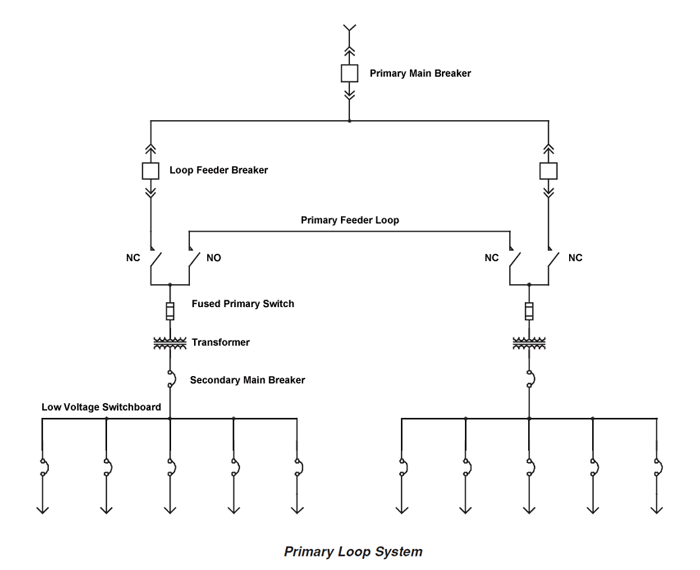
An outage to part of the primary loop system will be experienced after the failure of a feeder cable until the loop is switched to accommodate the loss of the cable. Photo: Square D.
The main advantage of the loop system over radial arrangements is that a failure of one transformer or feeder cable will not cause one part of the facility to experience a loss of service, and one feeder cable can be maintained without causing a loss of service.
Each primary loop is operated such that one of the loop sectionalizing switches is kept open to prevent parallel operation of the sources. An outage to part of the system will be experienced after the failure of a feeder cable until the loop is switched to accommodate the loss of the cable.
By operating the appropriate sectionalizing switches, it is possible to disconnect any section of the loop conductors from the rest of the system. A key interlocking scheme is normally used to prevent closing all sectionalizing devices in the loop.
6. Secondary Selective system
Another method of allowing a distribution system to remain in service after the failure of one component is the secondary selective system. In this system, each transformer secondary is connected in a typical double-ended unit substation arrangement.
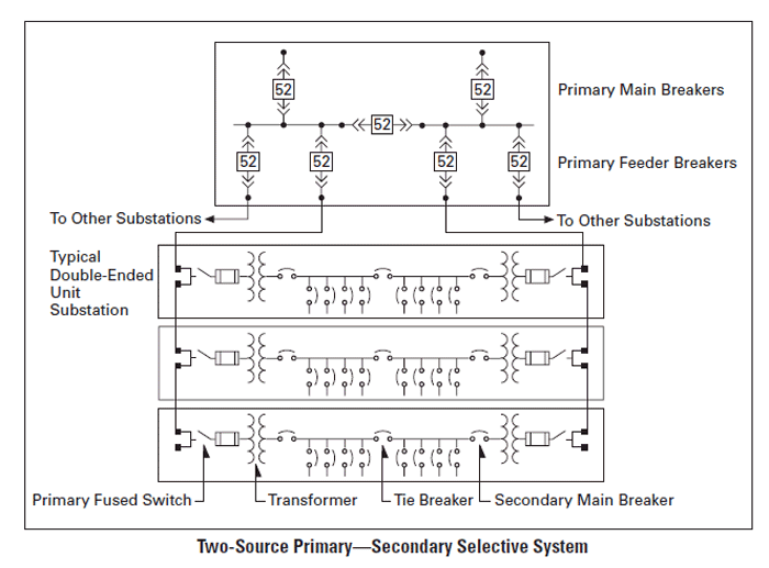
In the selective secondary arrangement, the secondary main circuit breakers and secondary tie breaker of each unit substation are either mechanically or electrically interlocked to prevent parallel operation. Photo: EATON
The two secondary main circuit breakers and the secondary tie breaker of each unit substation are either mechanically or electrically interlocked to prevent parallel operation. In the event that the secondary source voltage is lost on one side, manual or automatic transfer may be used to transfer the loads to the other side, thus restoring power to all secondary loads.
Related: Circuit Breaker Safety Interlock Systems Explained
7. Primary Selective system
If a single primary source is used in the secondary selective system, the loss of voltage at that source would result in a complete loss of the system. For greater reliability, duplicate sources from the power supply point using two primary main circuit breakers and a primary tie breaker are recommended.
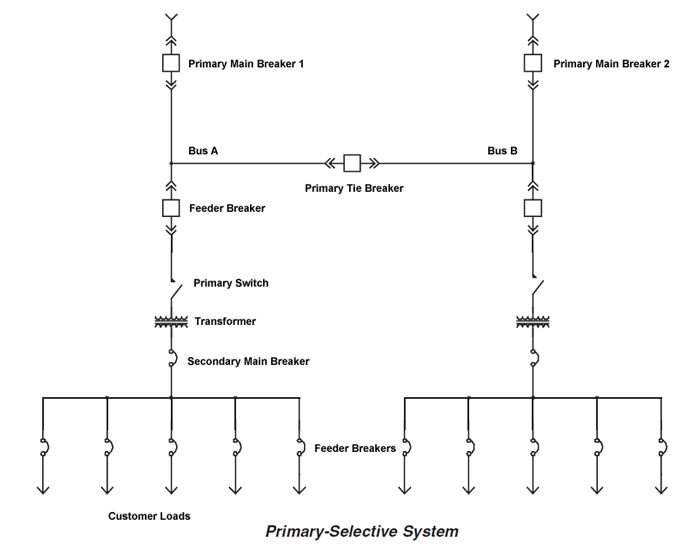
When combined with the primary selective system, greater reliability can be achieved with a secondary selective system. Photo: Square D.
In a primary selective system, two primary main breakers and a primary tie breaker are again either mechanically or electrically interlocked to prevent parallel operation. Upon the loss of a primary voltage source on one side, manual or automatic transfer may be used to restore power to all primary loads.
Metal-Clad switchgear is most commonly used with this type of arrangement due to the limitations of metal-enclosed load interrupter switches. Secondary radial or selective systems can be combined with the primary selective arrangement to create a composite system.
8. Sparing Transformer system
A larger-scale version of the secondary selective system is the transformer sparing scheme. It essentially replaces double-ended substations with single-ended substations and one or more “sparing” transformer substations, all of which are interconnected on a common secondary bus.
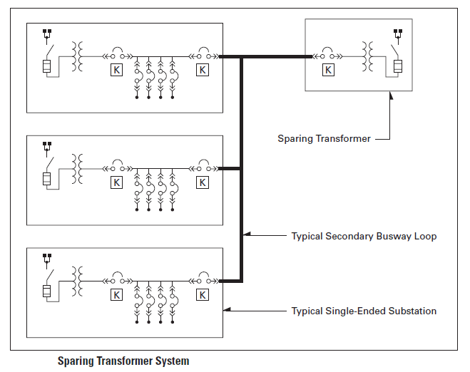
The sparing transformer electrical distribution system allows for good flexibility in switching. Photo: EATON
This type of electrical distribution system allows for good flexibility in switching. The sparing transformer supplies one load bus if a substation transformer fails or is taken off-line for maintenance.
All main breakers, including the sparing main breaker, are normally closed; the tie breakers are normally open. A transformer is switched out of the circuit by opening its secondary main breaker and closing the tie breaker to allow the sparing transformer to feed its loads.
Care must be used when allowing multiple transformers to be paralleled as the fault current increases with each transformer that is paralleled, and directional relaying is required on the secondary main circuit breakers to selectively isolate a faulted transformer.
An electrical or key interlock scheme is required to enforce the proper operating modes of this type of system, especially considering that switching is carried out over several pieces of equipment that can be in different locations from one another. An automatic transfer scheme may be utilized to switch between a failed transformer and an available transformer.
9. Secondary Spot Network system
In high-density areas where large loads must be served and a high degree of reliability is required, secondary network systems are often used. In this arrangement, several utility services are paralleled at the low voltage level, creating a highly reliable system.
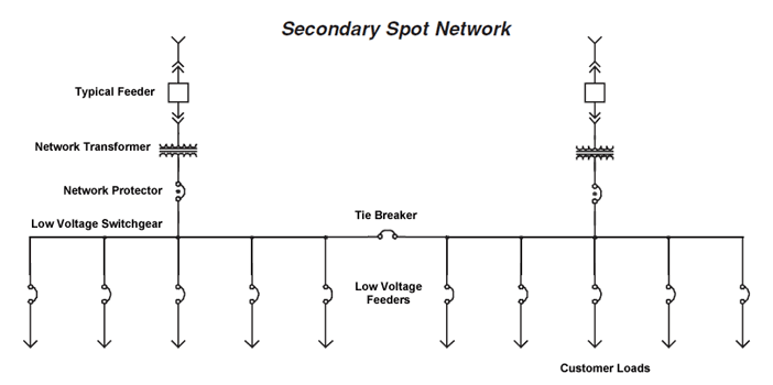
Secondary Spot Network systems are commonly used in buildings where a high degree of service reliability is required. Photo: EATON.
The major advantage of the secondary network system is the continuity of service. No single fault anywhere on the primary system will interrupt service to any of the system’s loads.
Network protectors are specially designed circuit breakers used at the transformer secondary to isolate transformer faults that are back-fed through the low voltage system. Most faults will be cleared without interrupting service to any load.
The common secondary bus is often referred to as the “collector bus.” Secondary Spot Network systems are commonly used in hospitals, high-rise office buildings, and institutional buildings where a high degree of service reliability is required from the utility sources.
Related: Network Protector Basics: Applications, Operation, and Testing
10. Composite Systems
The system arrangements discussed above are the basic building blocks of power distribution system topologies but are rarely used alone for a given system. To increase system reliability, it is usually necessary to combine two or more arrangements.
As reliability increases, so does complexity and cost. Economic considerations will usually dictate how complex of a system arrangement can be used, which will have a great deal of impact on how reliable the system is.