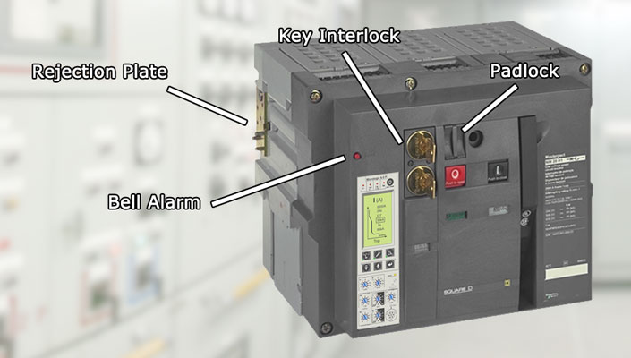
Photo: Square D Masterpact (Insulated Case)
Drawout circuit breakers are equipped with safety interlock devices required by various industry standards and certifying authorities. Interlock systems are integral to ensuring the safety of qualified personnel and protecting equipment from catastrophic damage.
During routine maintenance of circuit breakers, it is essential to operate all interlocks to confirm their proper functioning. Caution must be exercised to ensure that no interlock lever is bent, as this could compromise its functionality.
The standard interlock devices described below are exclusively used on drawout breakers, as stationary or fixed breakers do not necessitate interlocks. Options for interlock devices tailored to special circuit breaker applications are also available.
Contents
- Drawout Cradle Rejection Hardware
- Racking Mechanism Interlock
- Disconnect Position Interlock
- Closing Spring Interlock
- Positive Interlock
- Padlocks
- Key and Door Interlock
- Mechanical Interlock
- Blown Fuse Interlock
- Bell Alarm with Lockout
1. Drawout Cradle Rejection Hardware
In general, drawout circuit breakers of the same type and rating are interchangeable within their equipment compartments. However, circuit breakers of different frame sizes are not interchangeable.
To avoid the insertion of an incorrect type of circuit breaker into a drawout compartment, each breaker and its compartment are equipped with suitable “rejection hardware.” This hardware prevents the breaker from seating itself into the drawout rails or cubicle if it is the wrong type.
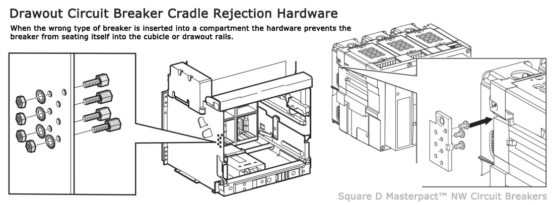
Rejection hardware works to prevent the insertion of circuit breakers with an inadequate interrupting capability, physically incompatible primary disconnects or an incompatible phase sequence, rejection interlock key plates are provided on both the circuit breaker and cassette Photo: Square D.
The rejection interlocks consist of steel pins affixed to the circuit breaker frame. As the breaker is pushed into the structure, the mating pins on the circuit breaker move past a set of corresponding pins in the compartment, ensuring compatibility between the circuit breaker and compartment. In the case of a mismatch between the circuit breaker and the cassette, the rejection pins will obstruct the insertion of the circuit breaker into the cassette before the racking mechanism is engaged.
Within any one physical frame size, drawout circuit breakers are available in a variety of continuous current and interruption ratings, some of which are incompatible with others. Additionally, doublewide circuit breakers may offer several phase sequence options, which are also incompatible.
2. Racking Mechanism Interlock
The purpose of the racking mechanism interlock is to prevent the breaker from moving from the connection position before it is in the open position. Typically, this interlock is a simple cover that must be moved aside to gain access to the drive shaft.
Related: Circuit Breaker Position and Indications Explained
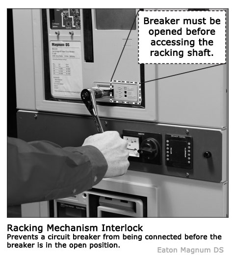
Racking interlocks prevent a circuit breaker from being connected to energized bus in the closed position. Photo: EATON Magnum DS.
The racking interlock cover can be connected to the trip button to ensure that the circuit breaker is open before attempting to rack. When the racking screw cover is open, it securely holds the trip button in place.
With the trip button held in, the breaker is maintained in a trip-free state, preventing contact movement during a mechanism closing cycle, particularly when the breaker is being racked in or out. It is crucial to always use the correct racking mechanism wrench for the process; otherwise, the trip-free interlock feature may not function as intended.
3. Disconnect Position Interlock
The Disconnect Position Interlock serves to obstruct the racking screw cover from being open when the racking mechanism is in the disconnected position.
As the cover is held open, the TRIP button becomes depressed. This ensures that the mechanism remains in a trip-free state, preventing any contact arm movement when the closing spring is charged by the Closing Spring Interlock.
4. Closing Spring Interlock
The closing spring interlock functions to release the closing spring as the breaker is racked out of its housing. This eliminates the risk of a fully charged breaker discharging after being removed from its compartment.
The racking mechanism arms and the crank are linked to a common shaft. During the racking out process, a pin attached to the crank moves through a slot in the mechanism linkage. This linkage is connected to a lever that engages with a pin on the closing solenoid armature linkage.
When the racking mechanism approaches the disconnected position, the crank pin reaches the end of the slot in the linkage. Continued motion of the racking mechanism causes the linkage to rotate the lever, moving the closing solenoid armature forward. The armature linkage then releases the prop, discharging the closing spring.
Important: Applying unnecessary force on the racking handle at the fully racked-out position may cause the lever to bind up the overall interlock. Under these conditions, continued application of this force will deform the linkage assembly.
5. Positive Interlock
The positive interlock is located on the circuit breaker frame. Its function is to maintain the breaker trip-free while it is being racked in or out between the connected and test positions.
As the breaker moves between the connected and test positions, the positive interlock engages with a ramp cam located in the breaker cubicle. This cam raises the interlock lever assembly, causing the trip shaft to rotate and preventing the trip latch from engaging with the secondary latch assembly roller. The breaker is held trip-free and cannot be closed during this interval.
6. Padlocks
Provisions are made on all circuit breakers to use padlocks to prevent the breaker from being closed. Padlock shackles are usually inserted through the trip button or racking screw cover. In either case, the shackle holds the trip button, keeping the mechanism trip-free.
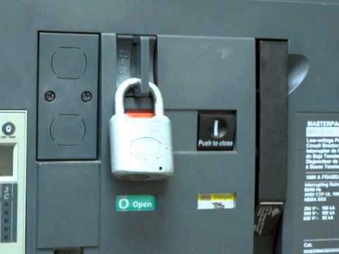
Padlock shackles are usually found through the trip button or racking screw cover. Photo: Youtube.
7. Key and Door Interlock
Optional interlocks include key interlocks and door interlocks. The function of the key interlock is to prevent an open breaker from being closed when the lock bolt is extended, and its key is removed.
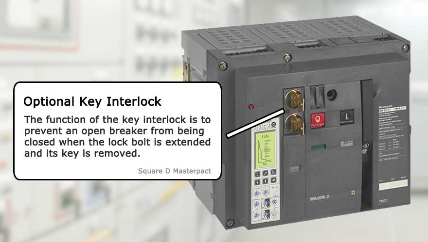
Photo: Key interlocks prevent an open breaker from being closed. Photo: Square D Masterpact.
Door interlocks prevent the breaker compartment door from being opened. On drawout breakers, these devices are mounted in the equipment and are part of the circuit breaker enclosure.
8. Mechanical Interlock
Families of mechanical interlocks are available to interlock the closing of two or three circuit breakers. The mechanical interlock holds one or more circuit breakers tripped (prevents closure) when the others are closed.
A lever assembly is mounted on each breaker, interfacing with the pole shaft and the tripper bar. The lever assemblies are interconnected with either cables or rods, depending on the relative orientation of the breakers.
Rods can be used only when the circuit breakers to be interlocked are vertically stacked. Cables can be used for any orientation of the breakers. Mechanical interlocks are available for both fixed and drawout circuit breakers and in both 2-way and 3-way versions.
9. Blown Fuse Interlock
Some circuit breakers have integrally mounted current limiters on the drawout breaker element. In the case of overloads and faults within the circuit breaker interrupting rating, the circuit breaker protects the limiters. For higher fault currents exceeding the circuit breaker rating, the limiters protect the circuit breaker.
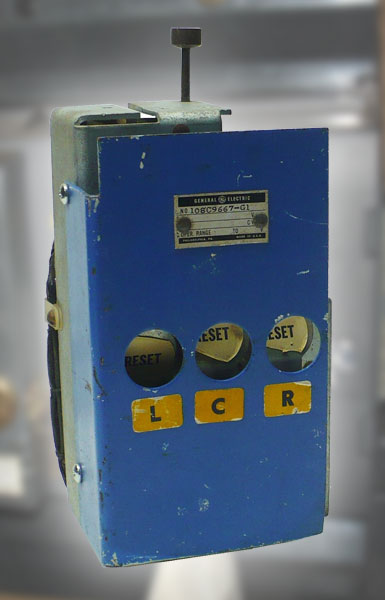
Example of a circuit breaker blown fuse indicator. Photo: General Electric
Interlock arrangements trip the circuit breaker whenever any limiter blows (open circuits). The circuit breaker cannot be reclosed on a live source unless there are only unblown limiters on the circuit.
The blown fuse indicator, located on the front of the circuit breaker, provides a visual indication when a current limiter in any phase has interrupted a short circuit. Additionally, a blown limiter sensing circuit ensures that a circuit breaker will be tripped when any current limiter has blown, preventing single phasing.
10. Bell Alarm with Lockout
The Bell Alarm with Lockout module prevents the reclosing of a circuit breaker after a trip until the Bell Alarm with Lockout is reset. It can only be reset by pressing the reset button on the module itself.
This module also provides a switch to remotely indicate that the circuit breaker has tripped. In addition to activation by protection trips, the Bell Alarm with Lockout accessory can be set up to interact with other accessories, such as Shunt Trip or Undervoltage Release coils.
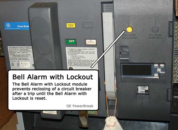
Circuit breaker bell alarm with lockout. Photo: GE Powerbreak.
In addition, the Bell Alarm with Lockout can provide normally open (NO) and normally closed (NC) alarm outputs available at the secondary terminal block located on the circuit breaker frame. These outputs return to their normal state when the Bell Alarm with Lockout reset button is pressed.