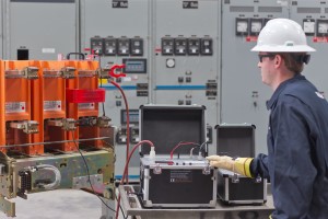
Its essential that circuit breakers be tested and maintained to ensure proper operation during electrical faults. Photo: Vacuum Interrupter Testing
When a fault occurs on the electrical power system, fast and reliable protection means everything. If a circuit breaker fails to clear the fault at that critical moment, the resulting damage can be disastrous in terms of both personnel injury and equipment damage.
Even though circuit breakers can be very reliable, they tend to gather dirt, moisture, and contaminants while in service. Breakers used in hostile environments can be exposed to various corrosive contaminants, which damage not only the insulation system but also metal components, including the main contacts inside air circuit breakers.
For these reasons and more, its essential that circuit breakers be tested and maintained to ensure proper operation during electrical faults. There are three basic electrical tests that should be performed on medium-voltage circuit breakers as part of a preventive maintenance program:
1. Contact resistance test
The main contacts and primary stabs need to be checked periodically to detect abnormal wear, inadequate lubrication, and loose pivot points inside the circuit breaker. Poorly maintained or damaged contacts can cause arcing, single phasing, and electrical fires.
Electrical resistance of the circuit breaker’s primary circuit is calculated by measuring the voltage drop across the line and load terminals for each phase. This test should be performed using a low voltage, direct current (DC) power supply (low-resistance ohmmeter) to pass current from line to load, with the circuit breaker in the closed position.
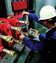
Contact resistance should be as low, and as even as possible, across all three phases of the circuit breaker. Photo: Arizona Electrical Apparatus
Test current should be equal to the rating of the circuit breaker or 100 amperes. Using a test current less than 100A is acceptable, but know that equipment manufacturers usually don’t recognize warranty claims based on a 10 ampere DLRO test.
Measured resistance values should be within 50% of each adjacent phase, and comparable to similar breakers as stated in NETA Maintenance Testing Specifications. The resistance should not exceed the factory test levels by more than 200% as stated in IEEE C37.09.
After maintenance testing, the contact resistance should be as low, and as even as possible, across the three phases of the circuit breaker. The actual contact resistance will vary, depending on the circuit breaker’s continuous current rating.
2. Insulation resistance test
The circuit breaker’s insulation system is a critical area that requires testing and evaluation. Insulation systems can weaken due to the heat created by arc interruption, especially if they are not routinely maintained.
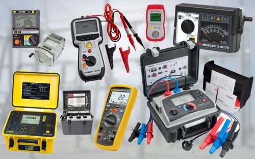
Insulation resistance test equipment. Photo: TestGuy.
Weak insulation can result in a catastrophic failure, especially during arc interruption. The insulation resistance test is useful for detecting major defects in the insulation system, but it can also be used as a final safety check before returning the breaker to service.
This test should be performed using a megohmetter phase-to-phase and phase-to-ground with the breaker in the closed position, as well as across the open contacts for each phase. Use the manufacturers recommended test voltage and acceptance values for this test.
When no factory recommendations are available, NETA Maintenance Specifications may be used (Table 100.1).
Control Wire Insulation Test
All circuit breaker control wiring should be insulation tested as it can easily be cut on sharp edges when moving the breaker in and out of its cell. It only takes a single wire shorted inside of the circuit breaker to prevent it from effectively clearing a fault. This could result in failure of the trip coil, charging circuit, or even the protective relay.
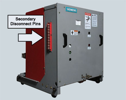
Measure insulation resistance of control wiring from the wire to the circuit breaker frame or chassis. Photo: Siemens GMI.
Perform this test by connecting all points of the secondary disconnect pins together and measure insulation resistance from the wire to the circuit breaker frame or chassis. Use caution when conducting this test, don’t apply high voltage to the spring charging motor or solid-state devices; isolate these items prior to insulation resistance testing.
Note: Power-factor or dissipation-factor testing should be considered as an additional test of the insulation system.
3. Dielectric withstand voltage test
Dielectric withstand is basically a hipot test. This test picks up where insulation resistance left off; it’s used to detect tracking, deterioration, and moisture in the insulation system at a much higher voltage.
AC Hipots are recommended for dielectric withstand testing circuit breakers. Photo: HV, Inc.
The use of an AC high potential test set is recommended when testing medium-voltage circuit breakers. Always use test voltages specified by the manufacturer. When recommendations are not available, or not provided, NETA Maintenance Specifications can be used.
Dielectric withstand testing is performed from the line side of each phase, with the breaker open, all other phases tied together and connected to ground. For vacuum circuit breakers, this test will also provide an indication of the vacuum bottle integrity. Use manufacturer provided test voltages to avoid potential damage to the bottle.
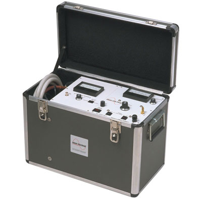
X-Radiation Emissions by Vacuum Interrupters
WARNING: X-Rays may be produced when a substantial voltage is imposed across open contacts in a vacuum. For vacuum interrupters, this means that X-Rays may be produced when dielectric (high-potential) tests are being conducted. During high-potential testing, the exposure is at low levels if test personnel remain at distances appropriate for the test voltage involved.
It should be understood that the vacuum bottle integrity test will only indicate the current state of the vacuum bottle and cannot predict the remaining life of the bottle, or determine the level of vacuum inside the interrupter. Vacuum interrupter testing using Magnetron Atmospheric Condition (MAC) Test Equipment can provide a viable means of determining the condition of vacuum interrupters prior to failure.
Other testing considerations for MV CB’s
In addition to these three basic tests, functional testing of the trip and close circuit should be performed via the manual controls. It’s even more important that the breaker be tripped via the protective relay to ensure that the relay and breaker are working together.
The protective relays should also be tested individually for functionality. In typical industrial power systems, over-current protection is the principal, and sometimes only, function provided by the relay; however, if there are other protective functions enabled, they should be tested as well.
Don’t forget to affix the appropriate field testing label for indication of the last maintenance date and the overall condition of the devices that have been tested and maintained.