
Transformer polarity is crucial when paralleling transformers to enhance capacity or connecting multiple single-phase transformers to create a three-phase bank.
Polarity marks on transformers indicate the connections where the input and output voltage share the same instantaneous polarity. This is important when connecting current transformers for relay protection and metering.
Transformer polarity is contingent on whether the coils are wound around the core clockwise or counterclockwise, as well as the configuration of lead connections. Polarity marks are commonly represented by symbols, such as dots or plus-minus marks, on both the transformer and its nameplate.
How to test transformer polarity
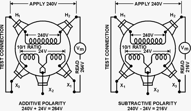
You can easily test transformer polarity by using a reduced voltage source to energize the primary winding. Begin by jumping the H1 terminal to the X1 terminal of the transformer. Then, connect a voltmeter between the H2 and X2 terminals. Apply a reduced voltage across H1 and H2, and record the voltage measured on the meter.
DANGER: Use the lowest AC voltage level possible to excite the winding and reduce potential hazards. An adjustable ac voltage source is recommended to keep the test voltage low.
You can easily test for transformer polarity by using a reduced voltage source to excite the primary winding. Photo: USBR.
If the measured value equals the sum of the high and low windings, the transformer is considered to have additive polarity. Otherwise, if the meter reads less than the applied voltage, the polarity is subtractive.
ANSI Rule of Thumb for Transformer Polarity
Another rule of thumb for determining transformer polarity comes from ANSI designations. According to these standards, when facing the low-voltage side of a single-phase transformer (the side marked X1, X2), the H1 connection will always be on your far left.
If the terminal marked X1 is also on your left, it indicates subtractive polarity. Conversely, if the X1 terminal is on your right, it signifies additive polarity.
Think of transformer polarity in terms of current direction. Whenever current flows through a polarity-marked terminal on the primary winding, the current leaving the secondary winding will travel in the same direction, exiting the terminal with the same polarity marking.
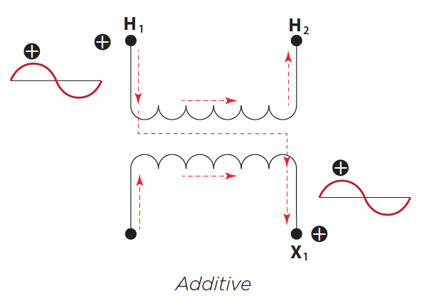
Whenever current is flowing through a polarity marked terminal on the primary winding, the current leaving the secondary winding will travel in the same direction, exiting the terminal with the same polarity marking. Photo: Mike Hennesey
Additive polarity is common for small distribution transformers. Larger transformers are generally subtractive polarity.
Transformer Bushing Arrangement
The placement of bushings in a three-phase transformer is also standardized. On the high-voltage side, the arrangement is H3, H2, H1, and H0 from left to right when facing the transformer.
When facing three-phase transformers from the low-voltage side, the low-voltage bushings are arranged X0, X1, X2, and X3 from left to right. It’s important to note that the terms “additive polarity” and “subtractive polarity” do not apply to three-phase transformers.
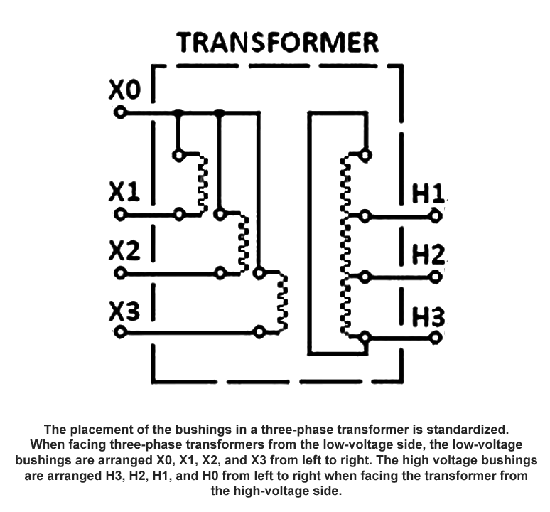
ANSI Three-phase transformer bushing arrangements.