Ground resistance testing, also known as earth resistance testing, is the process of measuring the resistance of a grounding system to the Earth. The purpose of this test is to ensure that the grounding system is functioning effectively and safely.
Accurate ground resistance measurements help identify and address any potential issues, such as inadequate grounding or high soil resistivity, which can affect the overall performance of electrical systems.
The procedures for earth resistance testing are referenced in IEEE Standard 81. Four of the most common methods of ground resistance testing used by test technicians in the field are discussed below:
2-point (dead earth) method
In areas where driving ground rods may be impractical, the two-point method can be used.
With this method, the resistance of two electrodes in a series is measured by connecting the P1 and C1 terminals to the ground electrode under test; P2 and C2 connect to a separate all-metallic grounding point (like a water pipe or building steel).
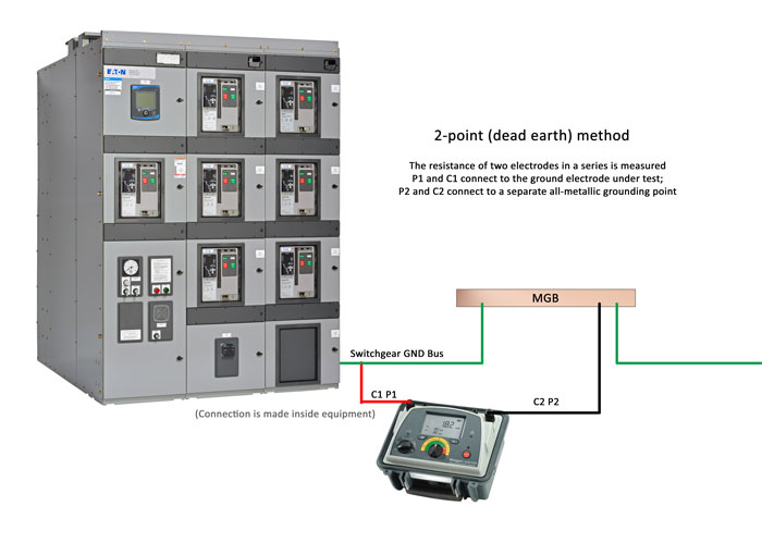
The two-point method is most effective for quickly testing the connections and conductors between connection points. Photo: TestGuy.
The dead earth method is the simplest way to obtain a ground resistance reading but is not as accurate as the three-point method and should only be used as a last resort. It is most effective for quickly testing the connections and conductors between connection points.
Note: The earth electrode under test must be far enough away from the secondary grounding point to be outside its sphere of influence to obtain an accurate reading.
3-point (Fall-of-potential) method
The three-point method is the most thorough and reliable test method; used for measuring resistance to earth of an installed grounding electrode.
The standard used as a reference for fall-of-potential testing is IEEE Standard 81: Guide for Measuring Earth Resistivity, Ground Impedance, and Earth Surface Potentials of a Grounding System.
With a four terminal tester, P1 and C1 terminals on the instrument are jumped and connected to the earth electrode under test while the C2 reference rod is driven into the earth straight out as far from the electrode under test as possible. Potential reference P2 is then driven into the earth, at a set number of points, roughly on a straight line between C1 and C2. Resistance readings are logged for each P2 point.
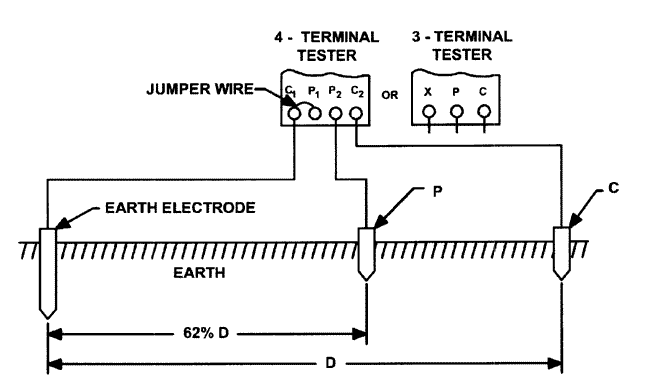
Fall-of-potential test method. Photo Credit: Megger
Measurements are plotted on a curve of resistance vs. distance. Correct earth resistance is read from the curve for the distance that is roughly 62% of the total distance between C1 and C2. There are three basic types of the fall-of-potential method:
- Full fall-of-potential: A number of tests are made a different spaces of P and a full resistance curve is plotted.
- Simplified fall-of-potential: Three measurements are made at defined distances of P and mathematical calculations are used to determine the resistance.
- 61.8 Rule: A single measurement is made with P at a distance 61.8% (62%) of the distance between C1 and C2.
Note: Fall-of-potential testing, and its modifications, is the only ground testing method that conforms to IEEE 81.
4-point method
This method is the most commonly used for measuring soil resistivity, which is important for designing electrical grounding systems. In this method, four small-sized electrodes are driven into the earth at the same depth and equal distance apart - in a straight line - and a measurement is taken.
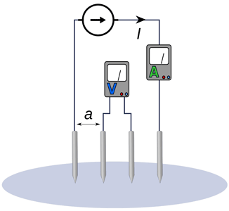
The Wenner four-pin method, as shown in figure above, is the most commonly used technique for soil resistivity measurements. Photo Credit: Wikimedia
The amount of moisture and salt content of soil radically affects its resistivity. Soil resistivity measurements will also be affected by existing nearby grounded electrodes. Buried conductive objects in contact with the soil can invalidate readings if they are close enough to alter the test current flow pattern. This is particularly true for large or long objects.
Related: What is Soil Resistivity and Why Does it Matter?
Clamp-on method
The clamp on method is unique in that it offers the ability to measure resistance without disconnecting the ground system. It is quick, easy, and also includes the bond to ground and overall grounding connection resistances in its measurement.
Measurements are made by “clamping” the tester around the grounding electrode under test, similar to how you would measure current with a multi-meter current clamp.
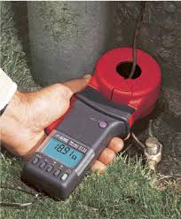
The clamp on method is unique in that it offers the ability to measure resistance without disconnecting the ground system. Photo Credit: AEMC
The tester applies a known voltage without a direct electrical connection via a transmit coil and measures the current via a receive coil. The test is carried out at a high frequency to enable the transformers to be as small and practical as possible.
For the clamp-on method to be effective, there must be a complete grounding circuit in place. The tester measures the complete resistance path (loop) that the signal is taking. All elements of the loop are measured in series. It is important for the operator to understand the limitations of the test method so that he/she does not misuse the instrument and get erroneous or misleading readings.
Some limitations of the clamp-on method include:
- effective only in situations with multiple grounds in parallel.
- cannot be used on isolated grounds, not applicable for installation checks or commissioning new sites.
- cannot be used if an alternate lower resistance return exists not involving the soil, such as with cellular towers or substations.
- results must be accepted on “faith.”