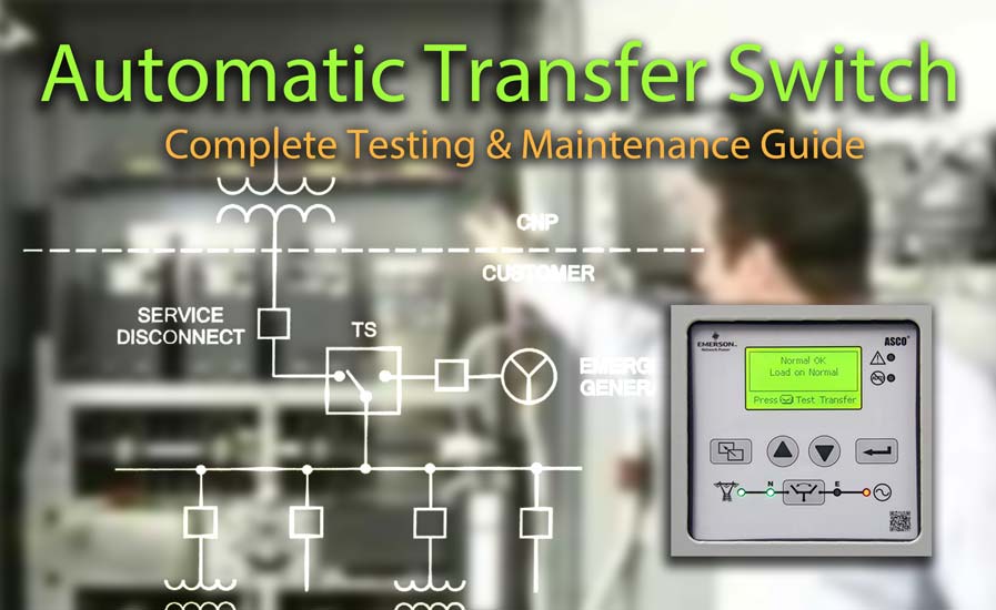
This guide provides information on the general inspection, operation and maintenance procedures of transfer switches. Photo Credit: Emmerson.
In emergency power systems, transfer switches are used to provide a continuous source of power for lighting and other critical loads, either automatically or manually. This transfer occurs by switching from the normal power source to an emergency power source in the event that the normal source voltage falls below preset limits.
Transfer switches are commonly used in various applications where continuous power supply is essential, such as hospitals, data centers, telecommunications facilities, emergency services, and critical industrial processes. They are also used in residential settings to switch power between the utility grid and a backup generator.
This guide provides information on the general inspection, operation, and maintenance procedures of manual and automatic transfer switches.
Important: Before doing any work on the transfer switch, de-energize all sources of power. Workers should be properly qualified for the work being performed.
Transfer Switch Testing and Maintenance Guide Contents
- Visual and Mechanical Inspections for Transfer Switch
- Main Contacts and Bolted Connection Inspection
- Manual Transfer Operation
- Insulation Resistance Tests
- Control Devices
- Automatic Transfer Tests
- Operation and Timing Tests
- Functional Test Procedure for Automatic Transfer Switch
- References
Visual and Mechanical Inspections for Transfer Switch
During initial acceptance testing, compare the equipment nameplate data with the project drawings and specifications to verify the correct system ratings (e.g., voltage, current, interrupting) and connections. Confirm the correct phase rotation, phasing, and synchronized operation as required by the application. Additionally, check for the proper labels and electrical warnings.

Typical Automatic Transfer Switch internal components. Photo Credit: Eaton.
Inspect the physical and mechanical condition of the transfer switch, including its anchorage, alignment, grounding, and required clearances. Ensure that all switch covers and barriers are installed and properly fastened.
Check that all cabled connections are correct and that the phase rotation of power from both sources matches. Conduct a general inspection of mechanical integrity to check for loose, broken, or badly worn parts.
The transfer switch should be clean and free of obstructions. When performing maintenance, conduct as-found tests prior to cleaning the unit. The switch should be inspected for any accumulation of dust, dirt, or moisture and cleaned by vacuuming or wiping with a dry cloth or a soft brush.
DO NOT use a blower to clean electrical apparatus since debris may become lodged in the electrical and mechanical components and cause damage.
Related: Cleaning Methods for Electrical Preventive Maintenance
Verify the appropriate lubrication on moving current-carrying parts and on any moving and sliding surfaces. Apply the appropriate lubrication on these parts when performing maintenance, if required.
Ensure that manual transfer warnings are attached and visible. Check engine start connections and verify the correct connection of all control wires.
Main Contacts and Bolted Connections
Remove the transfer switch barriers or arc chutes and check the condition of the contacts. Any surface deposits must be removed with a clean cloth (DO NOT USE EMERY CLOTH OR A FILE). If the contacts are worn excessively, they should be replaced.
Perform a contact/pole-resistance test. Microhm or dc millivolt drop values should not exceed the high levels of the normal range, as indicated in the manufacturer’s published data. If the manufacturer’s published data is not available, investigate values that deviate from adjacent poles or similar switches by more than 50 percent of the lowest value.
Note: Use the manual transfer operation to check the resistance of both normal source and alternate source contacts.
Inspect bolted electrical connections for high resistance using either a low-resistance ohmmeter, calibrated torque-wrench method, or thermographic survey. Investigate resistance values that deviate from those of similar bolted connections by more than 50% of the lowest value.
Bolt-torque levels should be in accordance with the manufacturer’s published data. In the absence of manufacturer’s published data, use ANSI/NETA Table 100.12.
Manual Transfer Operation
A manual operator handle is provided with the transfer switch for maintenance purposes only. Manual operation of the switch must be checked before it is operated electrically. Both power sources MUST be de-energized before the manual operation of the switch.
Insert the manual operating handle and operate the transfer switch between the Normal and Emergency positions. The transfer switch should move smoothly without binding. Return the switch to the Normal position, remove the handle, and return it to the storage holder provided.
Verify positive mechanical interlocking between normal and alternate sources. Adjust any optional accessories as required.
Typical one-line diagram for EPS with standby generator and transfer switch. Photo Credit: CenterPoint Energy
As Left Tests
When performing maintenance testing, if applicable, conduct as-found and as-left tests to document any changes in electrical test results.
Insulation Resistance Tests
Perform optional insulation-resistance tests on all control wiring with respect to ground. Apply 500 volts dc for 300-volt rated cable and 1000 volts dc for 600-volt rated cable for one minute.
Insulation-resistance values of control wiring should not be less than two megohms. For maintenance, compare values to previously obtained results but not less than two meghoms.
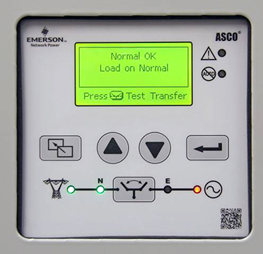
Automatic transfer switch solid-state controller, used to check status and perform transfer operations. Photo Credit: Emmerson
Important: Disconnect any plugs and fuses for units with solid-state components or for control devices that cannot tolerate the applied insulation resistance test voltage, follow manufacturer’s procedure.
Control Devices
Check for correct settings and operation of control devices. Calibrate and set all relays and timers in accordance with ANSI/NETA Section 7.9. Ensure that control devices operate in accordance with the manufacturer’s published data. Check the settings of all timers and adjust as necessary.
Automatic Transfer Tests
Perform automatic transfer tests:
- Simulate loss of normal power.
- Return to normal power.
- Simulate loss of emergency power.
- Simulate all forms of single-phase conditions.
Automatic transfers should operate in accordance with manufacturer’s design. For more detail on these tests, see the ATS functional testing procedure described below.
Operation and Timing Tests
Verify correct operation and timing of the following functions:
- Normal source voltage-sensing and frequency-sensing relays.
- Engine start sequence.
- Time delay upon transfer.
- Alternate source voltage-sensing and frequency-sensing relays.
- Automatic transfer operation.
- Interlocks and limit switch function.
- Time delay and re transfer upon normal power restoration.
- Engine cool down and shutdown feature.
Operation and timing shall be in accordance with manufacturer’s and system design requirements.
Functional Test Procedure for Automatic Transfer Switch
A general procedure for functional testing of an automatic transfer switch and standby generator is described below. Before proceeding, read and understand all manufacturer’s instructions and review the operation of all accessories provided.
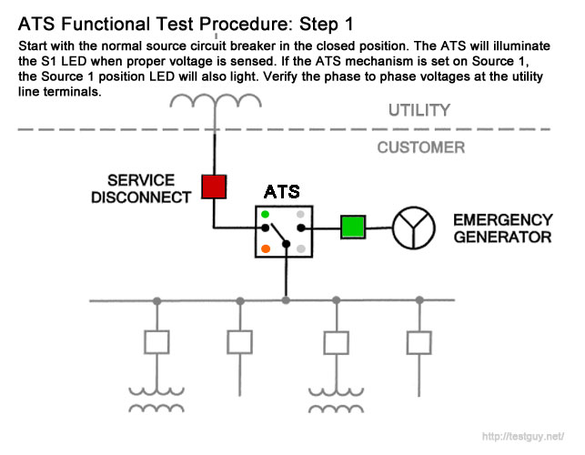
Step 1
To begin the test, close the normal source circuit breaker. The switch controller will illuminate the Utility Available LED (if equipped) when correct voltage is sensed. If the ATS mechanism is set on Source 1, the Source 1 position LED will also light. Verify the phase-to-phase voltages at the utility line terminals.
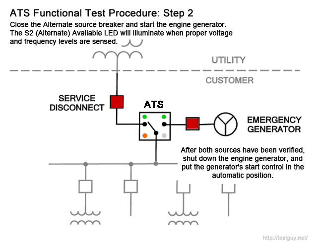
Step 2
Next, close the Alternate source breaker and start the engine generator. The S2 (Alternate) Available LED will illuminate when correct voltage and frequency levels are sensed. After both sources have been verified, shut down the engine generator and put the generator’s start control in the automatic position.
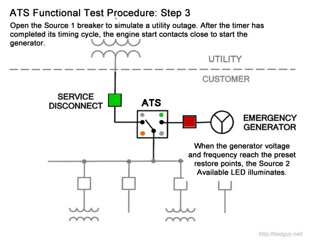
Step 3
Simulate a utility outage by opening the Source 1 (normal side) breaker. The delay to engine start timer begins its timing cycle. After the timer has completed its timing cycle, the engine start contacts close to start the generator.
Step 4
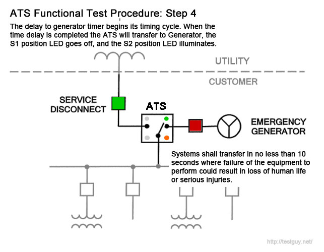
When generator voltage and frequency reach the preset restore points the Source 2 Available LED illuminates. Simultaneously, the delay to generator timer begins its timing cycle.
When the time delay is completed, the ATS will transfer to Generator, the S1 position LED goes off, and the S2 position LED illuminates. Systems shall transfer in no less than 10 seconds where failure of the equipment to perform could result in the loss of human life or serious injuries.
Step 5
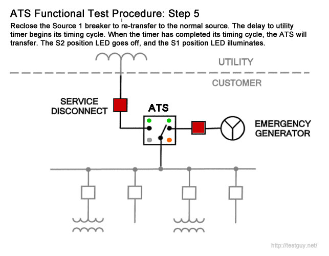
Reclose the Source 1 breaker to retransfer to the normal source. The delay to utility timer begins its timing cycle. When the timer has completed its timing cycle, the ATS will transfer. The S2 position LED goes off, and the S1 position LED illuminates.
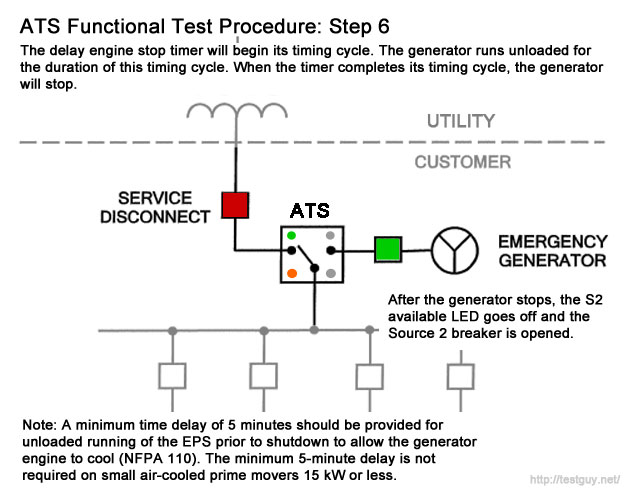
Step 6
The delay engine stop timer will begin its timing cycle, and the generator runs unloaded for the duration of this cycle. When the timer completes its timing cycle, the generator will stop.
The S2 Available LED goes off. A minimum time delay of 5 minutes should be provided for the unloaded running of the EPS prior to shutdown to allow for engine cool down (NFPA 110).
Note: The minimum 5-minute delay is not required on small air-cooled prime movers 15 kW or less.
Label as Required
Once all testing has been completed, apply a field testing label in accordance with NFPA standards indicating that the transfer switch is electrically and mechanically sound and suitable for service.
References
- NFPA 110: Standard for Emergency and Standby Power Systems, 2016 Edition
- Zenith ZTSH Operation and Maintenance Manual
- ANSI/NETA Standard for Maintenance Testing Specifications for Electrical Power Equipment and Systems
- ANSI/NETA Standard for Acceptance Testing Specifications for Electrical Power Equipment and Systems