The following inspections and tests should be performed before energizing newly installed low voltage wire and cable rated 600V or less.
Low voltage power cables are electrical cables used to transmit power at voltage levels lower than 1000 volts. They are commonly used in building and industrial electrical systems to distribute electricity to lights, motors, and other electrical equipment.
It is important to test and maintain low voltage power cables regularly because these cables are susceptible to degradation and damage over time due to factors such as heat, moisture, and physical stress. These conditions can result in a decrease in the cable’s electrical performance, leading to issues such as voltage drop, power loss, and increased resistance.
Regular testing and maintenance can help to identify and prevent these issues, ensuring that the cables continue to perform effectively and safely.
1.) Compare cable data with drawings and specifications. Pay attention to the number of sets, the cable size, routing, and insulation ratings. Note these items on the test sheet.
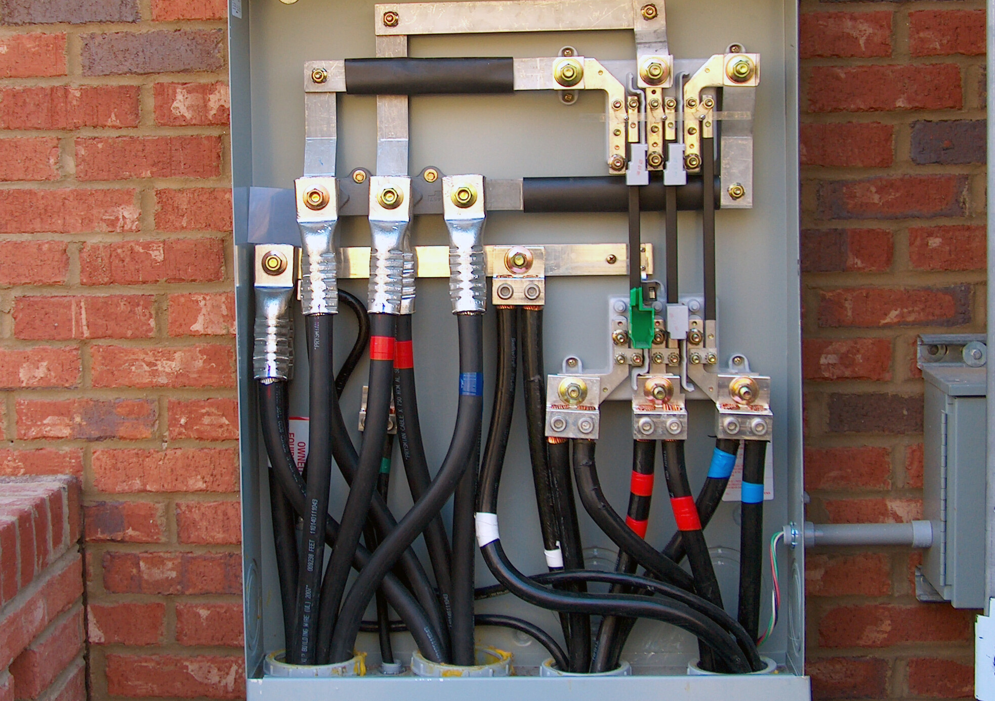
2.) Inspect exposed sections of cable for physical damage. Look at the condition of the cable jacket and insulation of exposed sections. Verify that the connection points match what is shown on the project single-line diagram.
3.) Inspect bolted electrical connections for high resistance using with the use of a low-resistance ohmmeter, calibrated torque-wrench or thermographic survey.
-
When using a calibrated torque wrench, reference ANSI/NETA Table 100.12 US Standard Fasteners, Bolt Torque Values for Electrical Connections.
-
If using a using a low-resistance ohmmeter, compare values to those of similar bolted connections and investigate values which deviate by more than 50 percent of the lowest value.
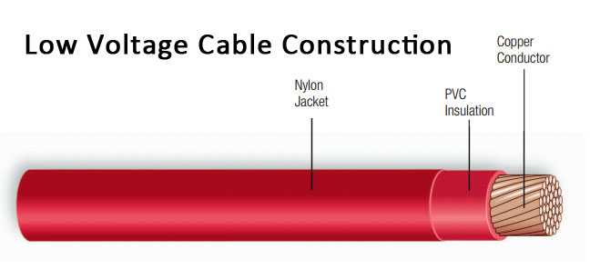
Look at the condition of the exposed cable jacket and insulation when performing a visual inspection on low voltage wire and cable.
4.) Inspect compression-applied connections by verifying that the connector is properly rated for the installed cable size and has the proper indentations.
5.) Perform an insulation-resistance test on each conductor with respect to ground and adjacent conductors. Test duration should be for one minute utilizing a voltage in accordance with manufacturers published data.
If no literature from the manufacturer is available, apply 500 volts dc for 300-volt rated cable and 1000 volts dc for 600-volt rated cable. Insulation-resistance values should be in accordance with manufacturer’s published data. If no data from the manufacturer exists, the values should be no less than 100 megohms.
6.) Perform continuity tests to ensure correct cable connection and phasing. Incorrect phasing can lead to problems with machine rotation and possibly electrical faults when energizing.
7.) Verify uniform resistance of parallel conductors using a low-resistance ohmmeter. Measure the resistance of each cable individually and investigate deviations in resistance between parallel conductors.