During its journey from the factory to the end user, a circuit breaker may encounter several potential challenges, including transportation vibrations, handling during unloading, and exposure to varying environmental conditions.
Although manufacturers conduct factory tests prior to shipping, it’s essential to perform additional checks and tests once the equipment arrives on-site. This ensures a new low-voltage circuit breaker has not been damaged, is in accordance with manufacturer specifications, and is ready for service.
Warning: Failure to perform these tests before de-energizing equipment may result in a serious hazard to equipment and/or personnel. Acceptance Testing should always be performed by qualified workers using test instruments that have been calibrated within the past 12 months.
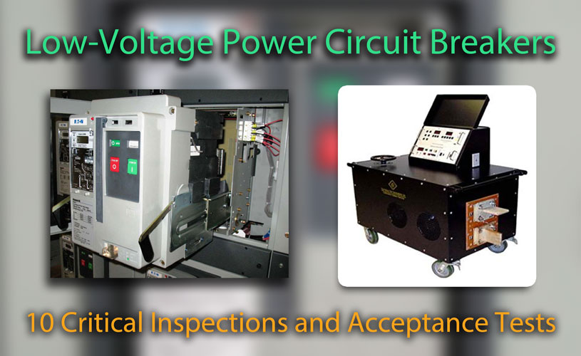
Visual and Mechanical Inspections
Prior to conducting electrical tests, circuit breakers undergo a visual inspection to verify the correct installation of equipment and check for any obvious signs of damage. Mechanisms and other devices, such as safety interlocks, are operated to ensure proper function before voltage is applied.
Related: Circuit Breaker Safety Interlock Systems Explained
Drawout circuit breaker connected inside switchgear cell. Photo: EATON.
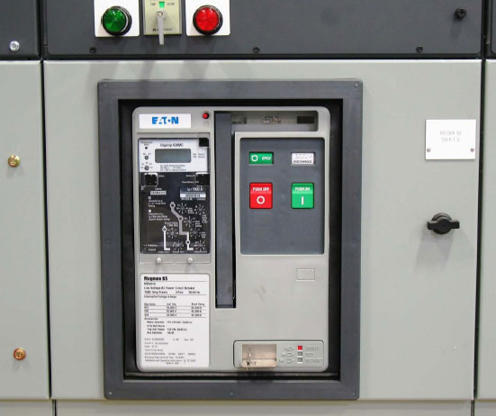
1.) Compare all nameplate data with jobsite drawings and specifications
Pay special attention to the circuit breaker frame size, ampacity, and interrupting ratings. If any ratings do not match the project specifications, it can lead to problems such as overloading, inadequate protection, non-compliance with standards, and safety risks.
Verify that the catalog number is correct to ensure that the proper accessories are installed and that the specified control voltage is accurate. Confirm the availability of all manufacturer-supplied maintenance devices for the circuit breaker, including charging/racking handles and lifts.
Note: Some circuit breakers may require special interlock keys or secondary blocks for testing outside of their cell. Consult manufacturers’ literature.
2.) Inspect the physical and mechanical condition of the circuit breaker
Ensure the breaker is clean with intact arc chutes. Contamination on the insulation surfaces can lead to tracking, while damaged arc chutes may not effectively extinguish electrical arcs during circuit interruption. This can lead to prolonged arcing, increased wear, and potential damage to contacts.
Inspect the main contacts and finger clusters for abnormalities. Verify that circuit breaker lubrication adheres to manufacturers’ specifications and mechanically charge, close, and trip the circuit breaker multiple times.
Related: 3 Critical Lubrication Points for Power Circuit Breakers
3.) Verify that the circuit breaker fits inside of its cell and is properly aligned.
Inspect the cell interior for any obvious signs of bent guides or other components. Ensure that the circuit breaker racking mechanism operates smoothly; it should require minimal effort to install/remove. Never force a breaker into a cell, and do not rack the circuit breaker onto live bus until all other testing is completed!
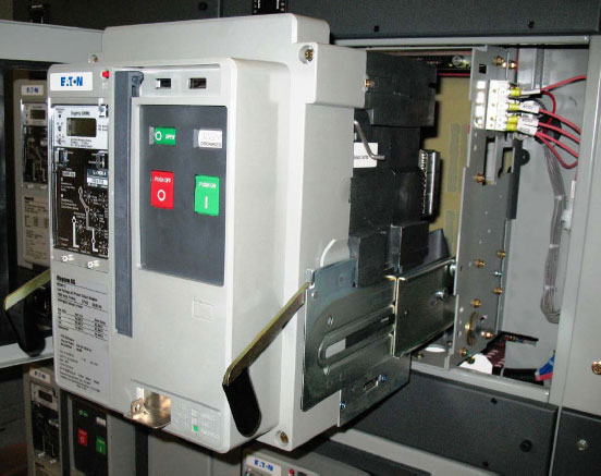
Verify that the circuit breaker fits inside of its cell and is properly aligned. Photo: EATON.
4.) Record as found and as left operations counter readings
Ensure the operations counter advances one digit per close-open cycle operation, this information is useful in determining maintenance intervals and estimating circuit breaker service life. Verify that the protective settings comply with coordination study recommendations.
Related: Electrical Power System Studies Explained
Make sure the trip unit battery is in good working condition. Without a sufficient charge, the trip unit will still operate but some settings such as local time and trip memory may not properly function.
Related: 5 Often Overlooked Tests for Power Circuit Breakers
Electrical Tests
After a circuit breaker is evaluated and found to be in adequate condition, technicians will proceed with electrical tests. The following checks will evaluate the condition of insulation, contact pressure, and interrupting capabilities before being placed into service.
5.) Inspect bolted connections, fuses, and contact/pole resistance using a low-resistance ohm meter
Microhm or DC millivolt drop values should not exceed levels within the normal range, as indicated in the manufacturer’s published data. This condition can lead to excess heating and contact wear. If no manufacturer’s literature can be found, investigate values that deviate from adjacent poles or similar breakers by more than 50 percent of the lowest value.
Related: Fastener Torque in Electrical Systems: Understanding the Basics of Mechanical Connections
6.) Insulation Resistance
Perform insulation resistance tests on each pole, phase-to-phase, and phase-to-ground with the circuit breaker closed, and across each open pole. These tests help identify any deterioration, contamination, moisture ingress, or other faults in the insulation.
Test duration should be one minute using a voltage in accordance with the manufacturer’s published data. If no literature from the manufacturer is available, apply 1000 volts DC for equipment with a nominal rating of 600 volts. Apply 500 volts DC for equipment with a nominal rating of 250 volts.
Measured values should typically be no less than 100 Megohms for equipment with a rating of 600V, and 25 Megohms for equipment rated 250 volts or less.
Related: Insulation Resistance Test Methods, A Beginners Guide
Important: Units with solid-state components could be damaged if not properly isolated (via removal of plugs and/or fuses) before applying test voltage. Be sure to follow all manufacturers’ recommendations when performing dielectric tests on solid state components.
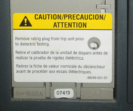
Solid-state components could be damaged if not properly isolated before applying test voltage. Photo: Square D.
7.) Control Wiring Tests
Control wires, which are used to transmit signals and control electrical devices, need to be properly insulated to prevent leakage, short circuits, and interference. Insulation resistance testing helps identify any deterioration, damage, moisture ingress, or contamination in the insulation of control wires.
Perform insulation-resistance tests on all control wiring with respect to ground. Apply 500 volts DC for 300-volt rated cable and 1000 volts DC for 600-volt rated cable for the duration of one minute.
Insulation-resistance values of control wiring should not be less than two Megohms. Control wires should be inspected for loose connections and damaged insulation.
8.) Test all basic trip unit functions via primary injection testing
Verify and document the long time pickup, long time delay, short time pickup, short time delay, instantaneous pickup, ground fault pickup and ground fault delay using a high current test set.
Primary injection should always be performed on new breakers before being placed into service to ensure proper CT ratio and polarity. Secondary injection may only be used after primary injection testing has first been completed.
Related: Primary vs. Secondary Injection Testing for Circuit Breakers
Ground fault protection will most likely need to be disabled by either rewiring or using the manufacturer’s recommended device. Saving ground fault tests for last will ensure the function is working properly before placing the circuit breaker into service.
Related: Ground Fault Protection Systems: Performance Testing Basics
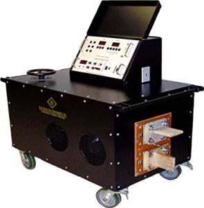
High current test sets verify that the circuit breaker ratio and polarity is correct. Photo: ETI.
9.) Verify the correct operation of any auxiliary features
Check trip and pickup indicators, zone interlocking, electrical close, shunt trip, trip-free, and anti-pump functions. Perform each test multiple times to ensure consistency.
Most of these tests, such as electrical charge and close operations can be performed while primary injection testing using the proper voltage listed on the circuit breaker nameplate. Other devices may require special equipment and procedures.
10.) Reset all trip logs and indicators after testing is completed
Verify the breaker is discharged, racked out, and that any auxiliary plugs removed for testing have been re-installed. Ensure the circuit breaker is ready to be energized and placed into service.