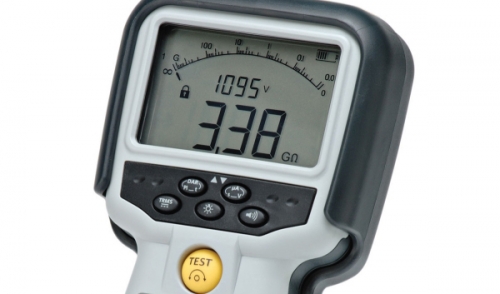
1kV Megohmmeter commonly used in the field to test electrical insulation. Photo: Megger
There are three different tests that can be performed with the Megohmmeter. A strong understanding of these common test methods is an important tool in gaining the ability to determine the condition and quality of electrical insulation.
Tests are typically conducted by applying a direct current (dc) voltage to the conductor under test and measuring the current that flows through insulation (called the “leakage current”) and into the non-current carrying metal parts of equipment.
1.) Short-Time or Spot-Reading Test
The short-time or spot-reading test is used for electrical apparatus with very small capacitance, such as a short run of house wiring or electrical panel.
Since large equipment is generally more capacitive, this test should only be used as a rough guide to determine the quality of insulation when no baseline is provided. It is important to note that temperature and humidity, as well as condition of the insulation affect the reading.
In this method, simply connect the Megohmeter across the insulation to be tested and apply the proper test voltage for a short, specific time period (60 seconds is usually recommended).
By recording these measurements over time, you gain a better basis of judging the actual condition of the insulation. Any persistent downward trend is usually fair warning of trouble ahead, even though the readings may be higher than the suggested minimum values.
Periodic readings found to be lower than recommended values may be ok as long as they are consistent. Refer to ANSI/NETA maintenance testing specifications for recommended insulation resistance values in the absence of manufacturers standards.
The One-Megohm Rule
As a general rule of thumb, insulation resistance should be approximately one megohm for each 1,000 volts of operating voltage, with a minimum value of one megohm. This is what is known as the “one-megohm rule.”
For example, a motor rated at 5000V should have a minimum insulation resistance of 5 Megohms. In practice, megohm readings should be well above this minimum value when insulation is new or in good condition.
2.) Time-Resistance Method
Unlike the spot-reading test, the time-resistance method is fairly independent of temperature and often can give you conclusive information without records of past tests.
This test method is sometimes also referred to as an “absorption test” because it is based on the absorption effect of good insulation compared to that of moist or contaminated insulation, which gives you a clearer picture of insulation quality even when a spot reading indicates an acceptable condition.
In this method, connect the Megohmeter as you would in the short-time or spot-reading test, while taking successive readings at specific times and noting the differences in the readings.
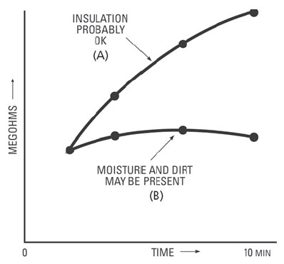
Typical curves showing dielectric absorption effect in a “time-resistance” test, made on capacitive equipment such as a large motor winding. Photo Credit: Megger US.
Good insulation shows a continual increase in resistance over a period of time (somewhere around 5 to 10 minutes) - this is caused by the charges that form on the plates of the capacitor which attract charges of the opposite polarity in the insulation, causing these charges to move and, thus, drawing current. Good insulation shows this charge effect over a time period much longer than the time required to charge the capacitance of the insulation.
Performing time-resistance tests on large switchgear, transformers, bushings, motors, and cables - especially at higher voltages - require high insulation resistance ranges and clean, consistent test voltages. These types of equipment should be tested with a line-operated Megohmeter.
3.) Dielectric Absorption Ratio and Polarization Index
The ratio of two time-resistance readings (such as a 60-second reading divided by a 30-second reading) is called a dielectric absorption ratio. If the ratio is a 10-minute reading divided by a 1-minute reading, the value is called the polarization index.
These value are very useful for determining insulation quality. When using hand-operated test instruments, it is much easier to run the test for only 60 seconds, taking your first reading at 30 seconds.
You will get the best results by running a 10 minute test using a line-operated test set, taking readings at 1- and at 10 minutes to obtain the polarization index. You can apply this value to the table provided below to obtain the relative condition of the insulation.
Any polarization index value less than 1.0 should be investigated according to NETA/ANSI acceptance and maintenance standards.
| Insulation Condition | Dielectric Absorption Ratio | Polarization Index |
|---|---|---|
| Dangerous | -- | Below 1.00 |
| Questionable / Poor | 1.00 to 1.25 | 1.00 to 2.00*** |
| Good | 1.40 to 1.60 | 2.00 to 4.00 |
| Excellent | Above 1.60** | Above 4.00** |
*These values must be considered tentative and relative – subject to experience with the time-resistance method over a period of time.
**In some cases, with motors, values approximately 20% higher than shown here indicate a dry brittle winding which will fail under shock conditions or during starts. For preventive maintenance, the motor winding should be cleaned, treated, and dried to restore winding flexibility.
***These results would be satisfactory for equipment with very low capacitance such as short runs of house wiring.