
Insulation testers come in a variety of sizes and output voltages depending on its specific application.
Most commonly referred to as simply a "megger," the insulation resistance test set (or Megohmeter) is used to determine the condition of insulation on various types of electrical equipment like cables, transformers and switchgear.
Tests are typically conducted by applying a direct current (dc) voltage to the conductor under test and measuring the current that flows through insulation (called the "leakage current") and into the non-current carrying metal parts of equipment. Contaminated insulation can be determined by observing the absorption current – or current absorbed by the insulation – over a specified period of time.
Insulation-resistance test data may be used to establish a trending pattern with deviations from the baseline information permit evaluation of insulation. The results of these tests (typically expressed in Megohms) are dependent on the temperature of the insulating material and the humidity of the surrounding environment at the time of testing; therefore all readings must be corrected to a base temperature, such as 20°C.
How much voltage can a be produced?
Insulation testers come in a variety of sizes and output voltages depending on its specific application. A handheld 1000V Megohmeter is usually sufficient for 600V class equipment while larger sets for use on high voltage apparatus can output up to 15,000V or more.
Megger Test Connections
There are three test terminals on an insulation resistance tester marked positive (+), negative (-) and Guard (G). Most basic measurements utilize only the positive and negative terminals, such as in cases when there is little possibility of adverse current paths that could affect the result.
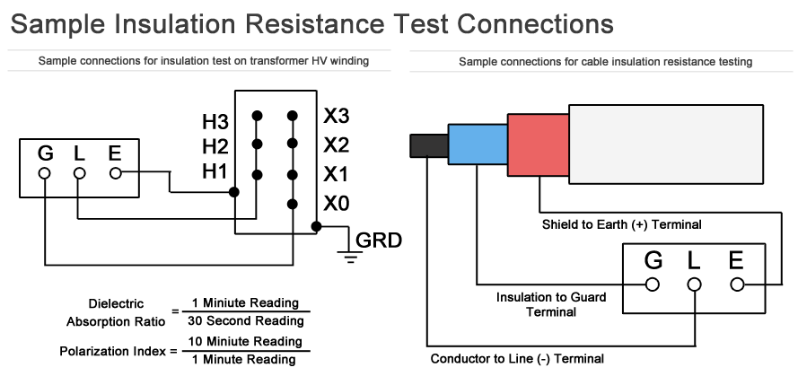
Sample insulation resistance megohmeter test connections for cable and transformer using Guard terminal.
Note: Handheld megohmeters with outputs of 1000V or less may not be equipped with a Guard terminal.
When testing at higher voltages, such as with cable or transformers, the guard terminal can be used to divert surface leakage from the measuring circuit. Not all insulation testers are equipped with a guard terminal.
High Voltage Safety
- Because the insulation resistance tester produces significant DC voltages, it should never be connected to an energized circuit. For this reason some testers are equipped with voltage sensing capabilities that will warn technicians when voltage is present on a circuit.
- The output of an insulation tester can destroy electronic circuits, which is why they should never be connected to electronic power supplies, PLCs, VSDs, UPS systems, battery chargers, or other solid-state devices.
- Insulation can hold a significant voltage charge for a period of time after the insulation resistance test is complete. Some testers have an automatic discharge feature that will discharge the insulation after testing; others do not.
- Most technicians will ground the circuit under test after the test is complete to verify the insulation is discharged. Some manufacturers recommend the insulation resistance tester remain connected to the circuit or component under test after the test is complete for up to four times as long as the test was conducted to ensure safe discharge.
Basic Care of Test Equipment
Basic care for the insulation tester includes keeping the instrument clean by wiping it periodically with a soft cloth, lightly dampened with soapy water, followed by a clean dry cloth. Never use alcohol or solvents to clean an insulation tester.
If equipped with rechargeable batteries, follow the manufacturer's recommended battery maintenance procedure. Before each use of the instrument visually inspect the test leads, prods and crocodile clips to confirm the insulation is not damaged or broken.
Check the continuity of the test leads by shorting them together and verify that the instrument measures a resistance less than one ohm on the display.