Heat is one of the leading causes of transformer failure. The main source of heat generation in transformers is caused by copper loss in the windings and core (I²R losses).
If heat inside a transformer is not properly dissipated, the temperature will continually rise, potentially damaging the insulation.
A transformer operating at just 10°C above its rating will reduce its life by 50%. It is easy to see why it is imperative to understand how transformers are cooled and how to detect problems in their cooling systems.
Transformers may have multiple load ratings that correspond to multiple stages of cooling. ANSI and IEEE require the cooling class of each transformer to appear on its nameplate. The cooling classification of a transformer, expressed in letters, designates the type of cooling system used.
Dry-Type Transformers
Dry-type transformers feature coils in open air and depend primarily on convection currents created by the transformer’s heat to generate airflow across the coils and maintain cool temperatures.
Louvers or screened openings are used to direct the flow of cool air across the transformer coils. Fans are often used to force the circulation of air through the case.
Related: Types and Construction of Power and Distribution Transformers

It is important to keep dry-type transformer enclosures clean and the area around them clear.
The kVA rating of a fan-cooled dry-type transformer is increased by as much as 33% compared to that of a self-cooled dry-type transformer of the same design.
It is important to keep dry-type transformer enclosures clean, and the area around them clear. Items placed near or against the transformer will restrict heat transfer around the enclosure.
As dirt accumulates on cooling surfaces, it becomes increasingly difficult for the air around the transformer to remove heat. Consequently, over time, the transformer temperature slowly rises unnoticed, reducing its service life.
Related: Cleaning Methods for Electrical Preventive Maintenance
Dry Type Transformer Cooling Classification
Cooling classes of dry type transformers are covered by ANSI/IEEE standard C57.12.01. Below is a summary of some common examples:
AA
Ventilated, self-cooled transformers have ventilation ports located in the outside walls of the enclosure. There are no fans to force air into and out of the enclosure, typically with no external fins or radiators. Cooler air enters the lower ports, is heated as it rises past windings, and exits through the upper ventilation ports.
AFA
Self-cooled (A) and additionally cooled by forced circulation of air (FA). These transformers have ventilation ports for fan inlets and outlets only. Normally, there are no additional ventilation ports for natural air circulation.
AA/FA
Ventilated, self-cooled (same as Class AA). These transformers have a fan or fans providing additional forced-air cooling. Fans may be wired to start automatically when the temperature reaches a pre-set value. These transformers generally have a dual load rating, one for AA (self-cooling natural air flow) and a larger load rating for FA (forced air flow).
ANV
Self-cooled (A), non-ventilated (NV). These transformers have no ventilation ports or fans on the enclosure and are not sealed to exclude migration of outside air, but there are no provisions to intentionally allow outside air to enter and exit. Cooling is by natural circulation of air around the enclosure. This transformer may have some type of fins attached outside the enclosure to increase surface area for additional cooling.
GA
Sealed with internal gas (G) and self-cooled (A). These transformers typically have a gas, such as nitrogen, SF6, or freon, to provide high dielectric and efficient heat removal. Cooling occurs by natural circulation of air around the outside of the enclosure. There are no fans to circulate cooling air; however, there may be fins attached to the outside to aid in cooling. The enclosure is hermetically sealed to prevent leakage.
Liquid Cooled Transformers
Liquid-filled transformers have coils immersed in an insulating medium, usually oil, which serves as both an insulator and provides an effective medium for removing excess heat.
Related: Insulating Liquids: Basic Properties, Types and Applications Explained
The cooling classification of a transformer, expressed in letters, designate the type cooling system used.
As transformer oil deteriorates through aging and moisture ingress, transformer oil samples should be periodically drawn and analyzed in accordance with ASTM insulating oil test methods.
Liquid-cooled transformer cooling classes underwent significant changes in the United States when IEEE Standard C57.12.00-2000 adopted the four-letter designation found on modern power transformers.
Modern Cooling Class Designations (2000 and Later)
First Letter: Internal cooling medium in contact with the windings
- O: Mineral oil or synthetic insulating liquid with fire point < 300°C
- K: Insulating liquid with fire point > 300°C
- L: Insulating liquid with no measurable fire point
- G: Gas insulated
Second Letter: Circulation mechanism for internal cooling medium
- N: Natural convection flow through cooling equipment and windings
- F: Forced circulation through cooling equipment (cooling pumps), natural convection flow in windings (non-direct flow)
- D: Forced circulation through cooling equipment, directed from the cooling equipment into at least the main windings
Third Letter: External cooling medium
- A: Air
- W: Water
Fourth Letter: Mechanism for external cooling medium
- N: Natural convection
- F: Forced convection
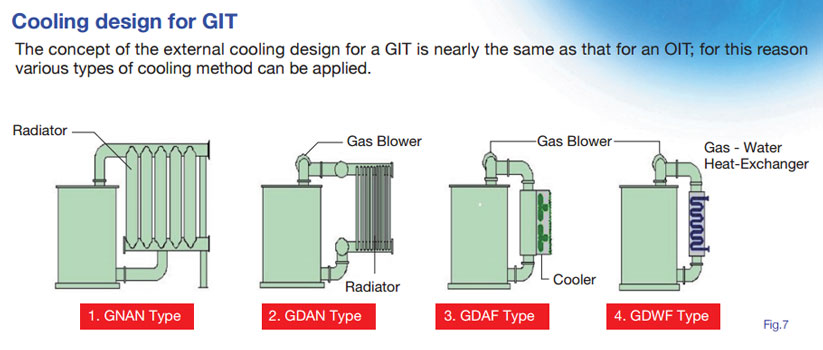
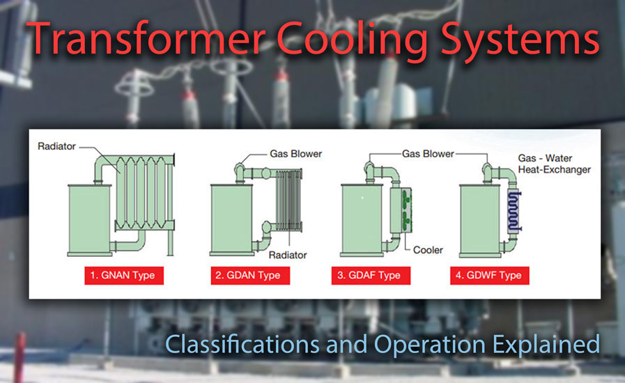
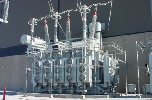
The cooling design of a Gas Insulated Transformer is nearly the same as that for an Oil Insulated Transformer. Photo: Toshiba.
Transformer Cooling Class Examples
Below, we look at some examples of modern liquid transformer cooling classes along with their designations prior to ANSI/IEEE C57.12.00-2000:
ONAN (OA)
Oil-immersed, self-cooled.
Transformer windings and the core are immersed in some type of oil and are self-cooled by the natural circulation of air around the outside enclosure. Fins or radiators may be attached to the enclosure to aid in cooling.
ONAN/ONAF (OA/FA)
Liquid-immersed, self-cooled/forced air-cooled.
Same as OA, with the addition of fans. Fans are usually mounted on radiators. The transformer typically has two load ratings, one with the fans off (OA) and a larger rating with fans operating (FA). Fans may be wired to start automatically at a pre-set temperature.
ONAN/ONAF/ONAF (OA/FA/FA)
Liquid-immersed, self-cooled/forced air-cooled/forced air-cooled.
Same as OA/FA with an additional set of fans. There typically will be three load ratings corresponding to each increment of cooling.
Increased ratings are obtained by increasing cooling air over portions of the cooling surfaces. Typically, there are radiators attached to the tank to aid in cooling.
The two groups of fans may be wired to start automatically at pre-set levels as temperature increases. There are no oil pumps. Oil flow through the transformer windings is by the natural principle of convection.
ONAN/ONAF/OFAF (OA/FA/FOA)
Liquid-immersed, self-cooled/forced air-cooled/forced liquid, and forced air-cooled.
Windings and core are immersed in some type of oil. This transformer typically has radiators attached to the enclosure.
The transformer has self-cooling (OA) natural ventilation, forced air-cooling FA (fans), and forced oil-cooling (pumps) with additional forced air-cooling (FOA) (more fans).
The transformer has three load ratings corresponding to each cooling step. Fans and pumps may be wired to start automatically at pre-set levels as temperature increases.
ONWF (OW)
Transformer coil and core are immersed in oil.
Typically a oil/water heat exchanger (radiator) is attached to the outside of the tank. Cooling water is pumped through the heat exchanger, but the oil flows only by natural circulation.
As oil is heated by the windings, it rises to the top and exits through piping to the radiator. As it is cooled, the oil descends through the radiator and re-enters the transformer tank at the bottom.
ONWF/ONAN (OW/A)
Transformer coil and core are immersed in oil. This transformer has two ratings.
Cooling for one rating (OW) is obtained as previously described. The self cooled rating (A) is obtained by Natural Circulation of air over the tank and cooling surfaces.
OFAF (FOA)
Liquid-immersed, forced liquid-cooled with forced air-cooled.
This transformer normally has only one rating. The transformer is cooled by pumping oil (forced oil) through a radiator normally attached to the outside of the tank. Also, air is forced by fans over the cooling surface.
OFWF (FOW)
Liquid-immersed, forced liquid-cooled, water cooled.
This transformer is cooled by an oil/water heat exchanger normally mounted separately from the tank. Both the transformer oil and the cooling water are pumped (forced) through the heat exchanger to accomplish cooling.
Old Cooling Class Designations (Prior to 2000)
| Letter | Designation |
|---|---|
| A | Air |
| FA | Forced Air (fans) |
| O | Oil |
| FO | Forced oil (pumps) |
| G | Gas |
| W | Water/oil heat exchanger |
Examples
| Letter | Designation |
|---|---|
| AA/FA | Ambient Air / Forced Air |
| AA/OA | Ambient Air / Oil (natural convection) |